Hi to everyone
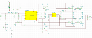
Currently I am building a MOSFET Audio amplifier based on LME49830 chip from TI. The scheme consists:
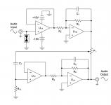
POWER SUPPLY -> PRE-AMPLIFIER -> POWER AMPLIFIER -> LOAD (for each channel)
My power supple contains 2 PSU, the first one delivering +-60V to the POWER AMPLIFIER BOARD and the second one supplying +-12V to the PRE-AMPLIFIER board. In order to accomplish this, I ordered a costumed Transformer made for my requirements which consists on one primary winding and two secondary windings each one with a center tap (or mid-point).
The problem is that these mid-points are in different potential so I don't know if I can just connect them.
My POWER AMPLIFIER board also needs the +-12V supply in order to supply a current mirror I am using for a chip.
How would GND connections be in this case? I am asking because the output of the PRE-AMP board is referenced to the center tap of the 2nd secondary winding (+-12V) and this output goes to the POWER AMP board which GND is the center tap of the 1st secondary winding.
The potential between the two center taps is about 7Vrms (I measured it with a multimeter).
My idea is to use a very low resistor (and high power) between these 2 center taps but I also want to use a GND star configuration in order to avoid GND loops.
I'll appreciate any help from you guys.
Thanks!
Currently I am building a MOSFET Audio amplifier based on LME49830 chip from TI. The scheme consists:
POWER SUPPLY -> PRE-AMPLIFIER -> POWER AMPLIFIER -> LOAD (for each channel)
My power supple contains 2 PSU, the first one delivering +-60V to the POWER AMPLIFIER BOARD and the second one supplying +-12V to the PRE-AMPLIFIER board. In order to accomplish this, I ordered a costumed Transformer made for my requirements which consists on one primary winding and two secondary windings each one with a center tap (or mid-point).
The problem is that these mid-points are in different potential so I don't know if I can just connect them.
My POWER AMPLIFIER board also needs the +-12V supply in order to supply a current mirror I am using for a chip.
How would GND connections be in this case? I am asking because the output of the PRE-AMP board is referenced to the center tap of the 2nd secondary winding (+-12V) and this output goes to the POWER AMP board which GND is the center tap of the 1st secondary winding.
The potential between the two center taps is about 7Vrms (I measured it with a multimeter).
My idea is to use a very low resistor (and high power) between these 2 center taps but I also want to use a GND star configuration in order to avoid GND loops.
I'll appreciate any help from you guys.
Thanks!
Attachments
It is almost certain that you are not measuring what you think you are measuring.The potential between the two center taps is about 7Vrms (I measured it with a multimeter).
Correct. You should use a very low value resistor with high power handling - usually known as a piece of wire.My idea is to use a very low resistor (and high power) between these 2 center taps but I also want to use a GND star configuration in order to avoid GND loops.
However, don't use the transformer CTs as the point of connection - this will guarantee buzz. Instead, connect each CT to its own reservoir capacitors junction, then connect the two junctions. This keeps charging currents out of the audio ground.
- Status
- This old topic is closed. If you want to reopen this topic, contact a moderator using the "Report Post" button.