You've got something going on there, but it isn't oscillation. It's the load pumping. If the circuit were unstable you would see a sharp peak in the impedance plot.
Could you perhaps humor me and load up the attached .asc and let me know how it works for you?
Attachments
"Hash", that is what it looks like, however most all of it is below 1uv.
Excellent! I did see your note about the 21st Century Maida meeting its noise/ripple spec.
")
The Maita regulator had about 200vdc input and 173vdc output, somewhere near 25v delta.
Were those voltages measured as DC voltages or is the 200 V DC input the lowest point in the ripple valley?
I'm sure you know already, but just in case: The 21st Century Maida Regulator has a 15 V drop-out voltage, so the valleys in the ripple need to be at least 15 V above the output voltage.
After the bench remodel I will try the adjustable dc supply with the Maita regulator to see what happens to the “hash” as the input dc voltage is adjusted.
That'd be cool.
Please tell me more about "a linear frequency sweep" I will be glad to run it.
It was brought up a page or two back. Now that I think about it again, I don't think it makes sense. An FFT is in linear frequency (the bin width is fs/N, where fs is the sampling frequency and N is the FFT length.
Tom
Could you perhaps humor me and load up the attached .asc and let me know how it works for you?
If solving the same equations in two places of the world do not yield the same result, I'd be seriously concerned.
As Jack noted, I haven't seen any issues with instability with the LT3080 when used in my 21st Century Maida Regulator either.
Tom
Could you perhaps humor me and load up the attached .asc and let me know how it works for you?
Would help if you had connected the gate of MOSFET M2
Would help if you had connected the gate of MOSFET M2
I'm sorry, but as per the picture in my previous post the gate of M2 *is* connected (to R7).
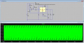
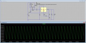
To make matters even more entertaining I've just redrawn the entire circuit as per your first post in this topic, even matching all of the parts in terms of exact type used. Et voila, the same result, it oscillates or has a bad hiccup, as can be seen in the picture below (Vout zoomed in).
And please don't take this as offensive or anything of that nature, I'm merely trying to figure out why this design falls apart in the simulator and appears to work in practice, in my experience it is usually the other way around.
If you could share you .asc that does work I'd appreciate it and look forward to taking a look at that, as my goal here is to understand why there's a discrepancy between simulation and reality.
Attachments
If solving the same equations in two places of the world do not yield the same result, I'd be seriously concerned.
As Jack noted, I haven't seen any issues with instability with the LT3080 when used in my 21st Century Maida Regulator either.
Tom
You'll agree with me that the schematic presented in the first post is significantly different from yours, hence no need to be concerned, we're not comparing apples to apples here.
Like you I take a rather analytical approach to engineering, so if something doesn't work on paper, or in the simulator, I'm not going to gamble that it will in practice. So I'm merely trying to understand why a circuit that is discussed in this topic, and apparently seems to work in practice, falls apart in the simulator.
You'll probably want the cathode of D1 connected to the gate of M2.
I'd also look at the loop stability around the CCS.
Finally, I'd double-check that Vgs(M2)-6.8-Iout*R2 > Vdropout(U1).
I'm not concerned about your schematic vs mine. I'm just making sure that others know we're comparing two different designs. I'm also saying that it is perfectly possible for the LT3080 to be stable in a circuit that's not too far off from yours.
I'm also curious about the line rejection (~PSRR) you're seeing with your regulator.
Tom
Go easy now Tom! This is something Jack found in the latest edition of ‘The Art of Electronics’ as per the first post in this topic. I can’t take credit for this design, I’ll take credit for breaking it in the simulator though, letting the virtual smoke out so to speak ...
I'm sorry, but as per the picture in my previous post the gate of M2 *is* connected (to R7)....
I do not know your schematics editor (and can't load your file).
To _my_ eye, R7 is 'too close' to M2. The end of the resistor, and the end of the gate, do not meet, but overlap. My editor will let part leads overlap without connecting. This has bit me several times.
However usually the sim will complain on error-check ("floating node"). I do not know if all sims do such checks.
Alright, I had an hour to spare this morning before heading off to work, so I dabbled with this for a bit whilst munching on breakfast. After going over things with a fine toothed comb all I could come up with is that the startup behavior isn't well defined and would cause for the hiccups as the LT3080 is having trouble regulating.
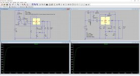
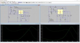
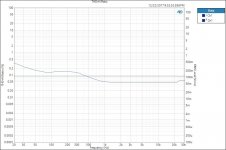
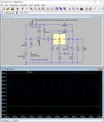
I added C3 and D3 to the original schematic which now properly define the startup behavior, the whole regulator now works fine through its voltage range by changing R5 in value. I also generated some PSRR plots and as icing on the cake reduced the original design to a simplified version without the CCS which shows good performance in the simulator as well.
Below are the schematics and graphs generated, on the left is the original design from the first post, on the right is my simplified version. Comments are welcome of course.
Attachments
@tomchr,
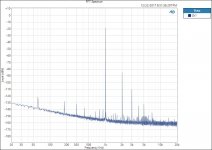
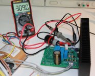
Did not want to keep you hanging. There is still not space for the oscilloscope. Same setup as original run. This time I cleaned up a few clip leads and twisted the power supply conductors. The FFT for the 21st Maita is much cleaner. See attached plots.
DT
Did not want to keep you hanging. There is still not space for the oscilloscope. Same setup as original run. This time I cleaned up a few clip leads and twisted the power supply conductors. The FFT for the 21st Maita is much cleaner. See attached plots.
DT
Attachments
Go easy now Tom!
What are you on about? I've pointed out a few details that I would verify in your circuit. How's that wrong? Isn't that what this forum is for? Would you rather that I don't share my experience? In case you forgot here's your original request:
Alright, perhaps you fine gentlemen can shed some light on this?
How would you like me to interpret this? Am I not in the "fine gentlemen" club or something? Just asking.
This is something Jack found in the latest edition of ‘The Art of Electronics’ as per the first post in this topic. I can’t take credit for this design, I’ll take credit for breaking it in the simulator though, letting the virtual smoke out so to speak ...
I'm aware of the design in The Art of Electronics. It looks like you've found an issue with it that wasn't caught by the original author. Or you've found an issue that's the result of inaccurate simulation models. Who knows?! I thought it would be interesting to find out and was of the impression that you requested help with this as per your quote above. Would you like my help in fixing this issue or would you rather that I spend my time elsewhere? I'm fine either way.
Tom
After going over things with a fine toothed comb all I could come up with is that the startup behavior isn't well defined and would cause for the hiccups as the LT3080 is having trouble regulating.
I'm doubtful of that hypothesis. At least I haven't seen any startup issues with the LT3080 in simulation.
I also generated some PSRR plots and as icing on the cake reduced the original design to a simplified version without the CCS which shows good performance in the simulator as well.
Nice improvement in line rejection. It'd be interesting to see if it holds up in practice.
Comments are welcome of course.
We'll see about that...
I suggest clipping the waveform to show the last 10-20 ms as you had in your original post.
Tom
Did not want to keep you hanging. There is still not space for the oscilloscope. Same setup as original run. This time I cleaned up a few clip leads and twisted the power supply conductors. The FFT for the 21st Maita is much cleaner. See attached plots.
Very cool. Thank you for following up. Yeah... It doesn't take much loop area to muck up a measurement at the uV level.
Tom
What are you on about?
I think we're starting on the wrong foot here, allow me to explain.
You wrote 'your regulator' a few times, and the original design posted isn't my design, I'm merely reporting on how it falls apart in the simulator and thus am questioning whether it works in practice, as apparently some of the members here have built it. So you made it sound like I'm responsible for its poor performance, to which I obviously object as it isn't my design.
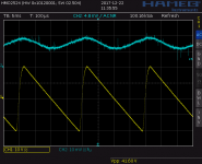
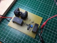
However, going forward, I've subsequently revised the design and verified it both in the simulator as well as in practice, as per the below pictured quick perf board prototype. That crude 30min prototype shows some impressive PSRR and that's without a decent PCB and a good look at current loops etc.
With 42Vpp at the input and 7mVpp at the output that's a factor of 42/7x10e-3=6000, or about 75dB, good enough for a perf board prototype in my book.
Have yourself a safe New Year's eve and all the best for 2018 Tom!
Attachments
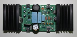
Congratulations for the nice result you had with a simple perf proto board, personally I will have used the TO220 version for the LT3080, not for power dissipation but for easy soldering
This is the version I have used in my power supply for an RIAA preampli (see photo) I wanted to integrate the rectifier and filtering on a single PCB with also the 6.3 V power supply for the heater therefor I only need a transformer to build the complete power supply...
I just need to add a pot on the white "V adjust" connector to set the output voltage between 50 V and 350 V and I can also use it as a laboratory power supply. I didn't made extensive test yet but a quick demo with the RIAA amplifier described here Merlin RIAA Preamp give very good result without any power supply noise I will do more test next year
Happy New-Year
Marc
This is the version I have used in my power supply for an RIAA preampli (see photo) I wanted to integrate the rectifier and filtering on a single PCB with also the 6.3 V power supply for the heater therefor I only need a transformer to build the complete power supply...
I just need to add a pot on the white "V adjust" connector to set the output voltage between 50 V and 350 V and I can also use it as a laboratory power supply. I didn't made extensive test yet but a quick demo with the RIAA amplifier described here Merlin RIAA Preamp give very good result without any power supply noise
I will do more test next year Happy New-Year
Marc
Attachments
By the way, you can examine the loop stability of a regulator or amplifier with an impedance plot in LTSpice -- from "group delay".
In real life, it's not always possible to break the control loop for a Bode plot:
https://www.picotest.com/articles/A...essment of Voltage Regulator Phase Margin.pdf
In real life, it's not always possible to break the control loop for a Bode plot:
https://www.picotest.com/articles/A...essment of Voltage Regulator Phase Margin.pdf
“Reverse-PSRR”
Jackinnj,
I googled “reverse-PSRR” and did not find much common usage of the term. I am not sure that I understand fully. Is PSRR v. reverse-PSRR something like line regulation v. load regulation? “PSRR” addresses disturbances caused on the raw DC side of the regulator. “Reverse-PSRR” addresses disturbances caused on the load side of the regulator.
Am I close?
Thanks DT
clip..... The Salas shunt is excellent in this regard, but it has some issues with "reverse-PSRR"
Jackinnj,
I googled “reverse-PSRR” and did not find much common usage of the term. I am not sure that I understand fully. Is PSRR v. reverse-PSRR something like line regulation v. load regulation? “PSRR” addresses disturbances caused on the raw DC side of the regulator. “Reverse-PSRR” addresses disturbances caused on the load side of the regulator.
Am I close?
Thanks DT
- Status
- This old topic is closed. If you want to reopen this topic, contact a moderator using the "Report Post" button.
- Home
- Amplifiers
- Power Supplies
- LT3080 High Voltage Floating Regulator