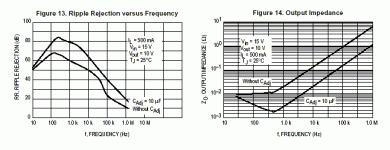
I think you should go and read the data sheet first of all
I don't know where you pulled those numbers out the air from but I think you have a misconception of what actually constitutes bandwidth for a regulator.
The bandwidth of a regulator at high frequencies as seen by the load is determined by the output capacitor and the bandwidth of the error amp is not the determining factor after a certain point. The gain bandwidth of the error amp will control the impedance as a function of frequency until the impedance rises to the point where it is higher than the impedance of the capacitor. That's why designers put capacitors on the output of regulators. Believe it or not three terminal regulators are used to power digital circuits with the right decoupling caps! It is quite possible to improve the noise and PSSR ratio over the bog standard implementations usually applied to 317/1086/337 type regulators. I think the idea was to milk the best performance out of a three terminal regulator with a simple circuit using good parts. There are applications where this circuit would be used as a preregulator for a more exotic regulators as well. I would think there is some interest in optimizing the circuit since even Mr. Carr weighed in on it. There are other chips with higher bandwidths that can be used for a regulator of about the same complexity (a couple more parts) and power dissipation as a 317........ but you would not be interested in that either I imagine.
Dear Dimitri:
How are you doing?
When an experienced designer uses a 3-terminal regulator together with fast digital or video-bandwidth circuitry, I doubt if he expects that the regulator by itself will be able to accomplish the entire task. Rather than expecting that the regulator itself be fast enough to keep the load circuitry happy, the designer primarily wants the regulator will keep the local bypass caps (placed at the load to reduce the effects of trace inductance) charged up, and it is these caps that will be called upon to supply the power to the load circuit as demanded.
OTOH, when using a discrete high-speed regulator, the designer may in fact want the regulator to do most of the work, and in this case local bypass capacitors may be used very sparingly.
In other words, the thinking differs for the above two situations, and in audio some well-known designers express a preference for the regulator-as-cap-charger philosophy, while other successful audio designers have stated that they want the regulator itself to have enough speed for the load. I use both concepts on occasion, depending on my mood and budget .
.
Besides, it is fun to try to make a Yugo perform like a Porsche (at least a 924 ).
).
Frank, if you connect C2 from the base of Q2 to the collector (ground), you _will_ have a low-pass filter, and the value of R2 will be added to the time constant to lower the corner frequency even more. So you get a lower drive impedance into Q2 because the value of R2 will no longer be added on top of the impedance curve of C2, plus you reduce the noise where it really matters - at the base of Q2.
I am not quite sure what you mean by R4/R8, as R9 corresponds to R4 in the negative schematic, while R8 in the negative corresponds to R3 in the positive.
hth, jonathan carr
How are you doing?
When an experienced designer uses a 3-terminal regulator together with fast digital or video-bandwidth circuitry, I doubt if he expects that the regulator by itself will be able to accomplish the entire task. Rather than expecting that the regulator itself be fast enough to keep the load circuitry happy, the designer primarily wants the regulator will keep the local bypass caps (placed at the load to reduce the effects of trace inductance) charged up, and it is these caps that will be called upon to supply the power to the load circuit as demanded.
OTOH, when using a discrete high-speed regulator, the designer may in fact want the regulator to do most of the work, and in this case local bypass capacitors may be used very sparingly.
In other words, the thinking differs for the above two situations, and in audio some well-known designers express a preference for the regulator-as-cap-charger philosophy, while other successful audio designers have stated that they want the regulator itself to have enough speed for the load. I use both concepts on occasion, depending on my mood and budget
Besides, it is fun to try to make a Yugo perform like a Porsche (at least a 924
Frank, if you connect C2 from the base of Q2 to the collector (ground), you _will_ have a low-pass filter, and the value of R2 will be added to the time constant to lower the corner frequency even more. So you get a lower drive impedance into Q2 because the value of R2 will no longer be added on top of the impedance curve of C2, plus you reduce the noise where it really matters - at the base of Q2.
I am not quite sure what you mean by R4/R8, as R9 corresponds to R4 in the negative schematic, while R8 in the negative corresponds to R3 in the positive.
hth, jonathan carr
Vicodin and posting don't mix......
"R8 in the negative corresponds to R3 in the positive."
Thanks, the base resistor is a small value resistor of 100 ohms or less
R8 or R3 are about a couple of orders of magnitude larger and determime the filter corner frequency. You also might not want to discharge the cap through the base of the transistor during fault conditions. Don't forget that Q1 and Q2 are high Hfe and Ft devices. you may not want to chuck the base resistors just yet........
Fred:
>R8 or R3 are about a couple of orders of magnitude larger and determime the filter corner frequency.<
I experimented with a wide range of values for R2, from 33 ohms up to 4.7kohms. In the interests of further circuit simplification I also tried deleting it entirely.
If you use SMD/MELF resistors and can physically get the junction of R3/R4 really close to the base of Q2, you may find that you don't need any additional base stopper resistors at all, in which case R2 can be eliminated. Ditto on the negative side.
But if you can't make a physically tight layout, and significant pcb or lead trace remains between the junction of R3/R4 and the base of Q2, I would leave R2 intact (and get the trace/lead length between R2 and the base of Q2 as short as possible), Otherwise Q2 may exhibit signs of instability.
Besides, Fred's point is valid. Fault protection should always be considered.
Look at the schematic, consider what you can accomplish with the board layout, and weigh the possibilities of some kind of fault condition occuring (including human error).
regards, jonathan carr
reading between the lines
"If you use SMD/MELF resistors and can physically get the junction of R3/R4 really close to the base of Q2, you may find that you don't need any additional base stopper resistors at all, in which case R2 can be eliminated. Ditto on the negative side."
I'm going to go out on a limb and assume that when your refer to the junction of R3/R4 you mean the connection to C2. I think that R3/R4 are large enough values to pretty well damp the trace inductance to their junction. The trace inductance and capacitor's internal and lead inductance of C2 is my real concern. Keeping C2 as close as possible to Q2's collector and base leads would be my first priority. I have a 5uF 200 V cap on my protoboard and a little damping seemed a very good idea. Shorting the input or output of the regulator will likely discharge the cap through the reverse biased base emitter junction of the transistor. The data sheet says not to exceed -5 volts from base to emmitter. If this supply gets shorted you will easily damage a transistor without current limiting provided by a base resistor. Too many years working on high reliability telecom circuits makes me worry about stuff like this. Also, I really wanted to avoid clamp diodes due to the RF paths provided by their junction capacitance. 100 ohms divided by a beta of 400 is 0.25 ohms and is going to add very little to the output impedance of the transistor follower. It is surprising how much there is to consider for a one transistor circuit isn't it?
Re: apples and oranges
but how do we know for sure that the circuit is correctly captured?
Fred Dieckmann said:What I ended up building is a one transistor addition to the three terminal regulator.
but how do we know for sure that the circuit is correctly captured?
Fred Dieckmann wrote: I don't know where you pulled those numbers out the air from but I think you have a misconception of what actually constitutes bandwidth for a regulator.
Dear Fred, I hope that you had measured the gain bandwidth of the error amp before you made attempt to improve the the LM3x7 regulator circuit. Otherwise you can read publications from AENG, which were cited here many rimes.
OK, you stick to regulator-as-cap-charger philosophy and would like to investigate the audibility of the output cap (and other components). Jonathan has already reported this.
You use the emitter follower in the feedback path, so you make the dc loop gain Vout/1.25V times higher than in datasheet circuit. You will get 10 time lower output impedance (about 2mOhm) in the frequency band from dc to several hundreds of Hertz. The ac loop gain remains unchanged. Another thing is that you eliminate the influence of the adjustment current as you drive the adjustment pin from low impedance node. But you add the temperature drift of BE junction -2,2mV/C to the initial reference 1,25V. The reference have the temperature stability -0.1mV/C in the range 25-75C, so you have worsened it significantly.
Is your “enhancement” valuable? From the components (and posts ) number point of view – yes. From the other points – doubtful…
Thank you, Jonathan, I will wait, I’m not in a hurry
Dear Fred, I hope that you had measured the gain bandwidth of the error amp before you made attempt to improve the the LM3x7 regulator circuit. Otherwise you can read publications from AENG, which were cited here many rimes.
OK, you stick to regulator-as-cap-charger philosophy and would like to investigate the audibility of the output cap (and other components). Jonathan has already reported this.
You use the emitter follower in the feedback path, so you make the dc loop gain Vout/1.25V times higher than in datasheet circuit. You will get 10 time lower output impedance (about 2mOhm) in the frequency band from dc to several hundreds of Hertz. The ac loop gain remains unchanged. Another thing is that you eliminate the influence of the adjustment current as you drive the adjustment pin from low impedance node. But you add the temperature drift of BE junction -2,2mV/C to the initial reference 1,25V. The reference have the temperature stability -0.1mV/C in the range 25-75C, so you have worsened it significantly.
Is your “enhancement” valuable? From the components (and posts
Thank you, Jonathan, I will wait, I’m not in a hurry
dimitri said:Is your “enhancement” valuable? From the components (and posts) number point of view – yes. From the other points – doubtful…
Hi, that's what we amature designers do: adding useless things like those "enhancements" so we can feel better,
I agree with you, dimitri. It seems enhancing things we don't know (and cannot capture correctly) is pretty funny.
only about an order of magnitude after all
'You will get 10 time lower output impedance (about 2mOhm) in the frequency band from dc to several hundreds of Hertz."
Yes, and similar improvements in PSRR. Changes approaching an order of magnitude are usually considered significant for most design work.
"But you add the temperature drift of BE junction -2,2mV/C to the initial reference 1,25V. The reference have the temperature stability -0.1mV/C in the range 25-75C, so you have worsened it significantly."
22mV over a 10 degree change times around (15/1.85 + 1) for 15 volts out. That's a little bit over 0.2 % I think I can live with that for a power supply voltage. I think you will find the temperature changes inside your audio equipment to be well under 10 degrees after it is warmed up. Even leaving the circuit on the bench and with the ceiling fan on I saw less than 10 mV drift after the circuit came up to temperature. I just don't see anything that bothers me about the temperature stability.
"You use the emitter follower in the feedback path, so you make the DC loop gain Vout/1.25V times higher than in datasheet circuit. You will get 10 time lower output impedance (about 2mOhm) in the frequency band from dc to several hundreds of Hertz. The ac loop gain remains unchanged. "
No the AC loop gain changes........ check the data sheet figures below for the LM317 below to see how much bypassing the ADJ terminal improves PSRR out and Zout over a large frequency range!
'OK, you stick to regulator-as-cap-charger philosophy and would like to investigate the audibility of the output cap (and other components). Jonathan has already reported this.'
Yes...... and I have discussed using good film caps also. The buffering of R3 and R4 with the follower allows much large resistor values and smaller cap values for a given corner frequency. This making the use of a quality film cap in the 1uF to 5uF region easily usable. Doesn't that fall under the capacitor quality issue?
There are better circuits for audio power supplies, not every one wants to go that far but would like to tweak the 317/337 up a few notches in performance. I have seen some sour grapes rational but nothing concerning the actual circuit, that makes it appear to not to deliver improvements in performance with a reasonable, simple and straight forward circuit, as desired by the original poster. I never imagined a one transistor circuit addition could generate any controversy. This one almost falls under the no brainer category and is real easy to go build and test. Try it.
Attachments
Dear Fred,
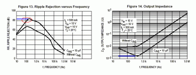
Your improvements in ripple rejection ratio and in output impedance are shown by blue lines.
Fred Dieckmann wrote “Yes, and similar improvements in PSRR”
As you can see from the data the circuit with Cadj=10uF _already_ has nearly the same PSRR as your one (red circle). I always thought that the ripple has the frequency 100-120Hz, why we need the improvement below?
Fred Dieckmann wrote “No the AC loop gain changes........ check the data sheet figures below for the LM317 below to see how much bypassing the ADJ terminal improves PSRR out and Zout over a large frequency range!”
Check yourself ... I have never wrote that we don’t need bypassing the ADJ terminal.
Attachments
I walk the line
"You use the emitter follower in the feedback path, so you make the dc loop gain Vout/1.25V times higher than in datasheet circuit. You will get 10 timeS lower output impedance (about 2mOhm) in the frequency band from dc to several hundreds of Hertz. The ac loop gain remains unchanged. "
The changes to the AC loop gain are what cause the PSRR and the output to improve and the benefits extend to pretty high frequencies. There are changes in the AC line voltages from very low frequencies all the way down to DC. Noise on the AC line and the rectification process cause voltage at the regulator input to extend to much higher frequencies than 120 Hz as can be seen by the non-sinusoidal shape of the ripple waveform. Diode bridges even generate considerable amount of RF noise There is a lot of noise that gets trough the transformer including RF through the interwinding capacitance. A regulator has an even harder job with line rejection than it does generating a low impedance source for AC load current. Despite the emphasis on output impedance, I think many audio designers will agree that PSRR is even more important. The large PSRR achieved by shunt regulators is their real advantage over series regulators, since for the same regulation topology, series and shunt regulators have the same output impedance. There may be some benefit from rejecting low frequency noise from the AC powerline.
The change PSRR and output impedance at low frequencies is due to the impedance of the cap becoming larger than the resistor it bypasses at low frequencies. At 60 hz a 10uF has an impedance magnitude of about 265 ohms. Larger resistor values made possible by the emitter follower can extend the rejection improvement down to extremely low frequencies with a fairly small value film cap. The value of the cap in the data sheet circuit is limited by the currents that a large cap can supply during a a short to the regulator.
The usual disclaimer. I am going to the doctor in an hour to see how long my head is going to hurt this bad after my surgery about a week ago. Vicodin makes me very stupid and numb but at least I don't hurt. And to think that I looked forward to feeling like this once and a while in my college days. As they say, youth is wasted on the young. I didn't even see the pun in that till I typed it.
  Proof of my mental state. Its too hard to solder like this so I will stick the PC for awhile.
Later,
Fried...... um I mean Fred
"You use the emitter follower in the feedback path, so you make the dc loop gain Vout/1.25V times higher than in datasheet circuit. You will get 10 timeS lower output impedance (about 2mOhm) in the frequency band from dc to several hundreds of Hertz. The ac loop gain remains unchanged. "
The changes to the AC loop gain are what cause the PSRR and the output to improve and the benefits extend to pretty high frequencies. There are changes in the AC line voltages from very low frequencies all the way down to DC. Noise on the AC line and the rectification process cause voltage at the regulator input to extend to much higher frequencies than 120 Hz as can be seen by the non-sinusoidal shape of the ripple waveform. Diode bridges even generate considerable amount of RF noise There is a lot of noise that gets trough the transformer including RF through the interwinding capacitance. A regulator has an even harder job with line rejection than it does generating a low impedance source for AC load current. Despite the emphasis on output impedance, I think many audio designers will agree that PSRR is even more important. The large PSRR achieved by shunt regulators is their real advantage over series regulators, since for the same regulation topology, series and shunt regulators have the same output impedance. There may be some benefit from rejecting low frequency noise from the AC powerline.
The change PSRR and output impedance at low frequencies is due to the impedance of the cap becoming larger than the resistor it bypasses at low frequencies. At 60 hz a 10uF has an impedance magnitude of about 265 ohms. Larger resistor values made possible by the emitter follower can extend the rejection improvement down to extremely low frequencies with a fairly small value film cap. The value of the cap in the data sheet circuit is limited by the currents that a large cap can supply during a a short to the regulator.
The usual disclaimer. I am going to the doctor in an hour to see how long my head is going to hurt this bad after my surgery about a week ago.
 Vicodin makes me very stupid and numb but at least I don't hurt. And to think that I looked forward to feeling like this once and a while in my college days. As they say, youth is wasted on the young. I didn't even see the pun in that till I typed it.
  Proof of my mental state. Its too hard to solder like this so I will stick the PC for awhile.
Later,
Fried...... um I mean Fred
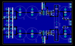
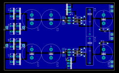
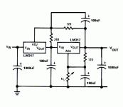
Since this thread has been revived, and when reading it I was drawn to the side of "stuff big bypass caps on the ADJ terminal" in the discussion, can someone confirm that I understood what posters were driving at and this would be a good circuit for me to build:
Attachments
- Home
- Amplifiers
- Power Supplies
- Improving the LM3x7 regulator circuit
