"Do we really need any component at all between
Vout and Adj if we have some kind of voltage reference connected
to Adj. It seems we don't."
Probably not.......... the voltage reference internal to regulator is bias
from the input. The only real concern is what happens to the circuit connected to this terminal during a fault condition like shorting the input to the regulator. There is also the possibility of connecting the ADJ to a nested feedback loop to improve the performance of the regulator.
Fred Dieckmann said:The only real concern is what happens to the circuit connected to this terminal during a fault condition like shorting the input to the regulator.
That is a good point. A diode from Adj to Vin could protect the
regulator, but then the voltage reference lives a dangerous life
instead. On the other hand, what worries me more in general,
not only in this case, is what might happen to the powered circuit
itself if the regulators fail. An LM3x7 is after all a pretty cheap
component to replace if it fails.
Not all circuits powered by dual rails would be happy if one of
the rails fail. Maybe there are solutions
to this problem around, although I can't remember seeing any, or
maybe nobody think it is worth bothering about. I think I might have
a simple solution to this problem, though, but it could potentially
have some nasty behaviour, so at the current stage I am hesitant
to post it since it may look like a finished design, while it isn't.
Beisdes, it is somewhat off-topic for this thread I think. however,
if somebody is interested in brainstorming about the idea I might
post it to hear opinions about it.
"However, the top of discussion is how to improve the 3 terminal regulator. Maybe by the time you get it improved, you won't need it."
There much better regulator circuits than three terminal devices but some desire them for their simplicity and the freedom from having to design a feedback voltage regulator Many people like to use them for preregulators as well. I think the origional intent was to explore very simple methods of improving thr performance of the three terminal regulator and not to have to design a whole new circuit. Do a search on the forum for "jung regulator" for much more serious design along the lines you are talking about.
There much better regulator circuits than three terminal devices but some desire them for their simplicity and the freedom from having to design a feedback voltage regulator Many people like to use them for preregulators as well. I think the origional intent was to explore very simple methods of improving thr performance of the three terminal regulator and not to have to design a whole new circuit. Do a search on the forum for "jung regulator" for much more serious design along the lines you are talking about.
One way for improving the 3X7 regulator
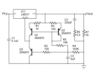
It really is worth using a current in between Vout and ADJ since the variation of the 1.25 volt reference in the regulator IC is the main contributor to PSRR and output impedance degradation. I have a circuit that should work pretty well with easily available parts. The transistors can be any thing with a very high Hfe at a milliamp or two. C1 should be a film cap and you can get away with something like 1uF if you what. I believe the voltage out is about 15 volts for the resistor values shown. I also have another design with a current jfet and a diode thermally coupled to the regulator with copper tape. The thermally coupling and the likely hood that you don't have a jfet CCS in your parts box may make this an easier circuit. You could get rid of Q1 and Q2 and put a resistor across Vout to ADJ but the performance of the circuit is not as good as with the current source.
It really is worth using a current in between Vout and ADJ since the variation of the 1.25 volt reference in the regulator IC is the main contributor to PSRR and output impedance degradation. I have a circuit that should work pretty well with easily available parts. The transistors can be any thing with a very high Hfe at a milliamp or two. C1 should be a film cap and you can get away with something like 1uF if you what. I believe the voltage out is about 15 volts for the resistor values shown. I also have another design with a current jfet and a diode thermally coupled to the regulator with copper tape. The thermally coupling and the likely hood that you don't have a jfet CCS in your parts box may make this an easier circuit. You could get rid of Q1 and Q2 and put a resistor across Vout to ADJ but the performance of the circuit is not as good as with the current source.
Attachments
Fred, I stumbled across your post while looking for a compact - yet well performing - regulator. How does it compare performance wise to the ordinary LM3x7?
I have some question:
1. What would the regulator for the negative rail look like apart from using a LM337 instead of the LM317?
2. And how much capacitance can be used at the output of the regulator while maintaining stability?
3. How can I calculate the output voltage? Input will be around 25v.
I'm in the process of drawing my first PCB (yes, I'm a noob as you might have figured from reading the above questions, sorry). The space is tight so there's no room for the Jung superregulator. The regulator will power 3 or 5 OPA134 for an L-R 12db/okt or 24db/okt crossover.
I hope you can answer some of my noob questions. I'm not exactly an EE...
Fred,
while this design is discussed, there is one thing I have wondered
since you first posted it. Q1 and Q2 looks like a multiplying current
mirror, but I don't quite get it if that is important and has some
advantage I don't get, or if Q2 could just as well be replaced by
a diode? Not that it matters much in practice if using cheap BJTs,
I am just trying to understand the design.
Live and let diode
Yes Christor, it can be a diode. I have actually built the circuit with a 1K resistor from Vout to ADJ since the extra complexity and cost of the transistor current source really didn't add to the performance. Something that occurred to me drawing the schematic, is that the ADJ terminal of the LM317 is sitting on top of a simple shunt regulator to ground (biased by a constant current source action, as well as bootstrapped by the three terminal regulator), a pretty neat trick for one transistor and a few passives. I will make some noise and PSRR measurements this week since my wife felt sorry for me* and let me buy a 24 bit sound card ( which can measure in the microvolt region without any external amp on the input to the sound card). I have another IC regulator circuit with an external voltage reference which is suprisingly simple for its performance. The design looks sort of interesting and should be a very substantial improvement over LM317/LT1086 type regulators (even with the shunt transistor circuit added to them). The LM317/transistor circuit appears very stable ( the voltage moves less than +/- 0.1% after the regulator warms up) and seems to survive output and input shorts without the addition of protection diodes. I have also built the jfet CCS version and with the addition of a diode thermally coupled to the regulator, it's output voltage is very stable as well.
I highly recommend the following for a very good overview on op amp based regulators:
http://tangentsoft.net/audio/opamp-linreg.html
http://home.comcast.net/~walt-jung/wsb/PDFs/Improved_PN_Regs.pdf\
http://www.e-insite.net/ednmag/archives/1997/010297/01di_03.htm
And last, but certainly not least!, from our resident regulator guru Andrew (ALW):
http://www.alw.audio.dsl.pipex.com/jung_schematic.htm
* I had sinus surgery to remove a polyp about the size of a ping pong ball and straighten my septum about 35 degrees. For those of you who have always wanted to punch me in the nose........ rejoice, I feel like I have been punched! I really almost hated to sleep through it. The image guided surgical tools project a cursor, realtime, onto three views of my sinus anatomy taken from a CT scan of my head and generated by a Sun workstation onto a large monitor. Sort of like GPS for driving around in my nose. I felt like I was in a Sci-Fi movie. They let me see the operating room but knocked me just as I was about to ask 50 questions about how it worked. The worst part was getting the packing pulled out two days after surgery. It is a 35 mm long plug forced into each nostril to a depth of 40 mm and pulled out rather quickly with forceps with no anesthesia. I told the doctor that I now know what a wine bottle feels like when you pull the cork out. For anyone that wants before and after pictures....... send me Email.
Yes Christor, it can be a diode. I have actually built the circuit with a 1K resistor from Vout to ADJ since the extra complexity and cost of the transistor current source really didn't add to the performance. Something that occurred to me drawing the schematic, is that the ADJ terminal of the LM317 is sitting on top of a simple shunt regulator to ground (biased by a constant current source action, as well as bootstrapped by the three terminal regulator), a pretty neat trick for one transistor and a few passives. I will make some noise and PSRR measurements this week since my wife felt sorry for me* and let me buy a 24 bit sound card ( which can measure in the microvolt region without any external amp on the input to the sound card). I have another IC regulator circuit with an external voltage reference which is suprisingly simple for its performance. The design looks sort of interesting and should be a very substantial improvement over LM317/LT1086 type regulators (even with the shunt transistor circuit added to them). The LM317/transistor circuit appears very stable ( the voltage moves less than +/- 0.1% after the regulator warms up) and seems to survive output and input shorts without the addition of protection diodes. I have also built the jfet CCS version and with the addition of a diode thermally coupled to the regulator, it's output voltage is very stable as well.
I highly recommend the following for a very good overview on op amp based regulators:
http://tangentsoft.net/audio/opamp-linreg.html
http://home.comcast.net/~walt-jung/wsb/PDFs/Improved_PN_Regs.pdf\
http://www.e-insite.net/ednmag/archives/1997/010297/01di_03.htm
And last, but certainly not least!, from our resident regulator guru Andrew (ALW):
http://www.alw.audio.dsl.pipex.com/jung_schematic.htm
* I had sinus surgery to remove a polyp about the size of a ping pong ball and straighten my septum about 35 degrees. For those of you who have always wanted to punch me in the nose........ rejoice, I feel like I have been punched!
I really almost hated to sleep through it. The image guided surgical tools project a cursor, realtime, onto three views of my sinus anatomy taken from a CT scan of my head and generated by a Sun workstation onto a large monitor. Sort of like GPS for driving around in my nose. I felt like I was in a Sci-Fi movie. They let me see the operating room but knocked me just as I was about to ask 50 questions about how it worked. The worst part was getting the packing pulled out two days after surgery. It is a 35 mm long plug forced into each nostril to a depth of 40 mm and pulled out rather quickly with forceps with no anesthesia. I told the doctor that I now know what a wine bottle feels like when you pull the cork out. For anyone that wants before and after pictures....... send me Email.* I had sinus surgery to remove a polyp about the size of a ping pong ball and straighten my septum about 35 degrees. For those of you who have always wanted to punch me in the nose........ rejoice, I feel like I have been punched! I really almost hated to sleep through it. The image guided surgical tools project a cursor, realtime, onto three views of my sinus anatomy taken from a CT scan of my head and generated by a Sun workstation onto a large monitor. Sort of like GPS for driving around in my nose. I felt like I was in a Sci-Fi movie. They let me see the operating room but knocked me just as I was about to ask 50 questions about how it worked. The worst part was getting the packing pulled out two days after surgery. It is a 35 mm long plug forced into each nostril to a depth of 40 mm and pulled out rather quickly with forceps with no anesthesia. I told the doctor that I now know what a wine bottle feels like when you pull the cork out. For anyone that wants before and after pictures....... send me Email.
I am happy for you that all went well. These are the less-desired-things-in-life that most of us need to go through while asking yourself the big Why ? question.
Best wishes,
Jean-Paul
Re: Live and let diode
OK, yes it seemed so to me, but I wouldn't trust my judgement.")
Since japanese transistors are mostly hard to find in Europe I
tend to always think of them as exotic and expensive devices,
so if you use one only as a diode, there has to be a reason,
I thought. However, I suppose those BJTs might be cheap
and common for you like a BC547 is here.
Don't worry, I've never wanted to punch you. You have all my
sympathy. I did a nose surgery about 15 years ago so I know
what it's like.
Well, I was actually awake when they butchered my nose, but
they didn't have any such fancy entertainment then. The only
entertainment was listening to the sound of knives carving bones
inside my skull.
Yes, I agree. The surgery itself wasn't much of a problem, but
the two days after, having my nostrils totally plugged with
cotton and dried blood, not being able to breathe through the
nose at all.
Fred Dieckmann said:Yes Christor, it can be a diode.
OK, yes it seemed so to me, but I wouldn't trust my judgement.
Since japanese transistors are mostly hard to find in Europe I
tend to always think of them as exotic and expensive devices,
so if you use one only as a diode, there has to be a reason,
I thought. However, I suppose those BJTs might be cheap
and common for you like a BC547 is here.
* I had sinus surgery to remove a polyp about the size of a ping pong ball and straighten my septum about 35 degrees. For those of you who have always wanted to punch me in the nose........ rejoice, I feel like I have been punched!
Don't worry, I've never wanted to punch you. You have all my
sympathy. I did a nose surgery about 15 years ago so I know
what it's like.
I really almost hated to sleep through it. The image guided surgical tools project a cursor, realtime, onto three views of my sinus anatomy taken from a CT scan of my head and generated by a Sun workstation onto a large monitor. Sort of like GPS for driving around in my nose. I felt like I was in a Sci-Fi movie. They let me see the operating room but knocked me just as I was about to ask 50 questions about how it worked.
Well, I was actually awake when they butchered my nose, but
they didn't have any such fancy entertainment then. The only
entertainment was listening to the sound of knives carving bones
inside my skull.
The worst part was getting the packing pulled out two days after surgery. It is a 35 mm long plug forced into each nostril to a depth of 40 mm and pulled out rather quickly with forceps with no anesthesia.
Yes, I agree. The surgery itself wasn't much of a problem, but
the two days after, having my nostrils totally plugged with
cotton and dried blood, not being able to breathe through the
nose at all.
sobazz said:What is the purpose of R7? SIMetrix seems to like the circuit better when R7 is removed.
It's probably there to provide a dummy load that
draws the required minimum current from the regulator. Even
if your simulator doesn't like (why would that one be a problem?)
your regulator will probably like it.
apples and oranges
What I ended up building is a one transistor addition to the three terminal regulator. The three transistor circuit doesn't add much to the performance and is not worth pursuing IMHO. Any good small signal transistor with an HFE of several hundred will work. Use a 1K resistor to program 1.25 mA through the transistor the error current through the voltage divider that sets the voltage will be 1.25mA divided by the Hfe of the transistor. You will want at least 100 times this current through the resistor divider to minimize the error. The transistor should have a base resistor of about 100 ohms to limit fault currents from discharge the bypass capacitor connected to its base and to provide better RF stability. All the bypass caps in the schematic are metalized film except the output electrolytics. About 0.1 to 0.47uF on the input to the regulator and 1 to 5 uF for the cap to ground connected to the base are fine. These are not that large size caps if using a metalized film cap. Stacked layer Polyesters would be about the smallest and polypropylene the largest (but with better performance). This circuit is not that critical for cap values. Put a 0.5 ohm resistor in series with the electrolytic output cap to ground. The main idea of all this was to use film caps of fairly low values with the transistor to make the impedance at the AJD terminal lower. There should be a large amount of leeway in the parts values for this circuit while still achieving a great performance improvement over the data sheet bypass circuit. I did not show the preloading resistors on the outputs but I would shoot for a minimum of 25 and preferably 50 to 100 mA. The output impedance is proportional to this current load and higher currents give lower output impedance. They also give more ripple on the raw supply so a balancing act is required to optimize both of these deign goals.
What I ended up building is a one transistor addition to the three terminal regulator. The three transistor circuit doesn't add much to the performance and is not worth pursuing IMHO. Any good small signal transistor with an HFE of several hundred will work. Use a 1K resistor to program 1.25 mA through the transistor the error current through the voltage divider that sets the voltage will be 1.25mA divided by the Hfe of the transistor. You will want at least 100 times this current through the resistor divider to minimize the error. The transistor should have a base resistor of about 100 ohms to limit fault currents from discharge the bypass capacitor connected to its base and to provide better RF stability. All the bypass caps in the schematic are metalized film except the output electrolytics. About 0.1 to 0.47uF on the input to the regulator and 1 to 5 uF for the cap to ground connected to the base are fine. These are not that large size caps if using a metalized film cap. Stacked layer Polyesters would be about the smallest and polypropylene the largest (but with better performance). This circuit is not that critical for cap values. Put a 0.5 ohm resistor in series with the electrolytic output cap to ground. The main idea of all this was to use film caps of fairly low values with the transistor to make the impedance at the AJD terminal lower. There should be a large amount of leeway in the parts values for this circuit while still achieving a great performance improvement over the data sheet bypass circuit. I did not show the preloading resistors on the outputs but I would shoot for a minimum of 25 and preferably 50 to 100 mA. The output impedance is proportional to this current load and higher currents give lower output impedance. They also give more ripple on the raw supply so a balancing act is required to optimize both of these deign goals.
Attachments
Fred: In the quest to make a silk purse from a sow's ear, interestingly enough, I also made a souped-up 3-terminal regulator circuit strikingly similar to yours. However I placed C2/C5 in your circuit directly at the base of Q2, to lower the drive impedance into Q2.
The cap used here turned out to be surprisingly audible, so I would suggest doing some swapping and listening. My own preference seemed to be tied to a good high-frequency impedance curve on the cap. OS caps and tantulums sounded better to me than any normal electrolytic tried, including audiophile as well as industrial grades.
hth, jonathan carr
I am glad you asked since I didn't get my message across, my fault
"Is this correct values?"
Absolutely not........... The idea is to make R3 R4 large to get a good low frequency corner for the filter. R3 should be 10K or above (probably not greater than 50K for the transistor base current to be small in comparison to the current through R3) I am using an A970 and C2240 for the transistors but anything with a beta of 400 or more at 1 mA will work. BC550 and BC560 would probably work very well and as would the 2N5087 and 2N5210. The Hfe for the ZTX450 and ZTX550 might be a little low but might work with adjusting the value for R4 and R9 to compensate for the larger base current. The electrolytic on the output should be in the 220uF to 1000uF range and don't leave out the series resistor. Quality and not quantity is what one should look for in the caps used.
Sorry I was vague, it was 4 in the morning.........
Fred
jcarr said:Fred: However I placed C2/C5 in your circuit directly at the base of Q2, to lower the drive impedance into Q2.
The cap used here turned out to be surprisingly audible, so I would suggest doing some swapping and listening. My own preference seemed to be tied to a good high-frequency impedance curve on the cap. OS caps and tantulums sounded better to me than any normal electrolytic tried, including audiophile as well as industrial grades.
Is it a way to form a LF filter to avoid HF noise entering the base of Q2 ?
Have you tested with an additional cap across R4/R8 (> 100uF) ? According to ALW (see here), this cap seems to do a nice job.
Well, it's not exactly the same purpose, but I was wondering...
Edit : Sorry Fred, was typing while you replied... My additional cap question is in the case C4 is directly connected to Q2's base...
- Home
- Amplifiers
- Power Supplies
- Improving the LM3x7 regulator circuit