At moment I would not frighten the differences, positions, between +, -, ground. I would create a one-side-pcb. Or freewired. Without a shield on a second side. Or with.
But try try try and tell. I will learn a lot.
Which amps do you build? If preamps too, than use the same psu, not another, not an different - do not collect differences,-)
But try try try and tell. I will learn a lot.
Which amps do you build? If preamps too, than use the same psu, not another, not an different - do not collect differences,-)
Hi Abdiel,
Designs in posts 57 and 58 are good, IMHO. The difference between them is that the design in post 58 lets you create GND connection off board should your amp design call for it.
Regards,
Oleg
Yes, exactly!
I need one faston for power amps, one for speaker connections and the third for chassis connection. The last connection is for voltage levels monitoring(protection circuit).
cumbb said:At moment I would not frighten the differences, positions, between +, -, ground. I would create a one-side-pcb. Or freewired. Without a shield on a second side. Or with.
But try try try and tell. I will learn a lot.
Which amps do you build? If preamps too, than use the same psu, not another, not an different - do not collect differences,-)
I wrote somewhere I will be using ESP P101 mosfet amps, hi-power versions. I already made them and they sound excellent. But most amps which were designed good sound the same for my ears. In time I'll change the amps with my own design.
I'm building an entire integrated amplifier, including pre amplifer(volume, tone and balance control). I'll also have full digital control over the amp via Android/iOS applications over Bluetooth. Still don't know which preamps to use.
I will make another thread in near future when everything will be finished.
Great amp, great design. Just one complementary-parts-stage. I would integrare an active bias-regulator/control.
To beat this design you would need a not-complementary-parts-design. And a step further: With only one psu, just (+) or (-). Or, final, a se.-)
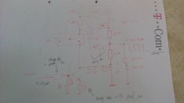
May be you need just passive tone-controls. There is a differential-"preamp"-) I built this design - with only one (+)-psu, without this pre. Less "sound" in my mind. Every source does drive easy.
Fine.
To beat this design you would need a not-complementary-parts-design. And a step further: With only one psu, just (+) or (-). Or, final, a se.-)
May be you need just passive tone-controls. There is a differential-"preamp"-) I built this design - with only one (+)-psu, without this pre. Less "sound" in my mind. Every source does drive easy.
Fine.
Last edited:
Yes I do. You try to achieve the "perfect" board with minimal impedance and then you ruin it with 1,32mm wire connected to pad? Seriously? Then all wires could be 1.32mm wide, why bother?
A typical thermal relief connection increases resistance by 0.1 mOhm and inductance by 0.1 nH compared to direct connection. Your incomplete GND in post #32 adds some mOhm and many nH. All wires made of 1.32 mm tracks adds some n*10 nH and n*10 mOhm. This is why.
If I wanted a fuse, I would have added it.
That thermal relief act as fuse at more than 100 A per each.
Your starter for PCB based calculations...
Saturn PCB Design - Microstrip calculator || Stripline calculator || Differential pair calculator || Via current calculator || PCB trace current calculator || Planar inductor calculator || Padstack calculator || Crosstalk calculator
If I was going to lay out a power supply (and I often do) I would firstly:
Lay it out from input to output, with no loop back...
Minimise the number of boards (1) minimising cabling.
Use exactly the correct amount of copper for the required current, no more no less.
Rout all AC as bus bar routing.
Rout the rest as either bus bar routing or power tracks over the return plane, my choice would depend on supply topography and other factors. The aim is to provide low inductance highish capacitance supply lines, with a low impedance path for high frequency noise as there is plenty of this in domestic (and other) environments, as a DIY product will more than likely be in a less than optimum shielded enclosure.
Slit the power supply into the relevant sections on the layout.
Follow the creapage and clearance rules, for high voltage supply's I would us a 4 Layer PCB with all high voltage tracks on inner layers and only pads on the outer layers for soldering.
And a common mode choke on the mains input is a must.... with differential mode chokes if you want, same on the power output, but with Pi-filters instead of differential mode chokes on their own....
Job done....
@Pafi
I guess my words were misunderstood. When I said I'll do another design, I meant I wish to change some things based on design on post #22. Not "I'll do it better than you". If I knew better, I would have not asked.
Anyways, I've made a new design. Removed cap/resistor for chassis, put + and - fastons closer to GND.
I've also reverted back + and - lines(bottom layer) so they are very close to each other as on post #22, which was intended. I also put GND plane on whole top layer, except in the middle.
That middle is a very important part of it. If current have to go around it, then it means impedance goes higher.
As you can see, I left a bit of space in the middle and I've split the GND plane where connectors are so I can get an "Y".
I hope you don't confuse your "Y" with Y axes I referred to as a direction.
Is this desired or not?
In this case not. It makes currents concentrated near connectors. This is bad, since makes GND potentials different.
You said I should keep Y,
No. Keep GND continuous in Y direction too, that was my advice. Your "Y" topology is indefinite for me.
but on one of the posts you said I should minimize the loop for first capacitor,
Every capacitors, not only first. I said also to make loops (not random loops, but operating current loops through capacitors) similar.
yes, mistaken.which is what I have now, for both + and - planes, each plane's 1st capacitor returns directly to rectifier. Or am I mistaken here?
I can also use 1 rectifier and then the entire top layer as GND makes sense to me perfectly.
You are right in that continuous GND is more important if you use 1 rectifier. But output impedance is also affected by GND plane.
I'm just confused because it seems nobody understands what I'm trying to do, use 2 rectifiers.
And others are confused, because you didn't state clearly this in the beginning. I thought you use2. But I prefer using 1 rectifier. If a design works well with 1 rectifier, then it will work well with 2 also. The other way can be problematic.
@Pafi
"Note: using 2 diode bridges, 35A which are not on the schematic."
So you were giving me the ideas for PCB and you didn't event read the post entirely nor checked the schematic... Awesome engineering.
So are the last PCBs ok?
@cumbb
Yes, P101 is an awesome amplifier. Currently using them with 300VA toroid, 4x4700uF caps @ ±35VDC, with only one MOSFET output pair and they rock. But so does any other amp I've built or tried. I still have to make something like Elektor's Crescendo but I don't expect any difference in sound.
I wish not to "surpass" P101 sound since I don't believe it will sound any better, I just want to learn how to design amplifiers. At least the basics.
I would like to use a solid state preamplifier. Although I can't hear any difference in using different opamps or solid state opamps since a good opamp is(or should be) transparent.
Do you have a schematic for the preamplifier you used? Send me a PM.
I would guess you have never seen an 100A fuse.That thermal relief act as fuse at more than 100 A per each.
Agreed.That middle is a very important part of it. If current have to go around it, then it means impedance goes higher.
Nope.I hope you don't confuse your "Y" with Y axes I referred to as a direction.
Ok, understood.In this case not. It makes currents concentrated near connectors. This is bad, since makes GND potentials different.
You should explain, for example, how C1 or C5 do not have direct returns when they are connected directly to rectifiers. Or we are not on the same page again or one of us is missing something obvious.Quote:
which is what I have now, for both + and - planes, each plane's 1st capacitor returns directly to rectifier. Or am I mistaken here?
yes, mistaken.
Ok. Agreed.You are right in that continuous GND is more important if you use 1 rectifier. But output impedance is also affected by GND plane.
This is a line from my #1 post.And others are confused, because you didn't state clearly this in the beginning. I thought you use2. But I prefer using 1 rectifier. If a design works well with 1 rectifier, then it will work well with 2 also. The other way can be problematic.
"Note: using 2 diode bridges, 35A which are not on the schematic."
So you were giving me the ideas for PCB and you didn't event read the post entirely nor checked the schematic... Awesome engineering.
So are the last PCBs ok?
@cumbb
Yes, P101 is an awesome amplifier. Currently using them with 300VA toroid, 4x4700uF caps @ ±35VDC, with only one MOSFET output pair and they rock. But so does any other amp I've built or tried. I still have to make something like Elektor's Crescendo but I don't expect any difference in sound.
I wish not to "surpass" P101 sound since I don't believe it will sound any better, I just want to learn how to design amplifiers. At least the basics.
I would like to use a solid state preamplifier. Although I can't hear any difference in using different opamps or solid state opamps since a good opamp is(or should be) transparent.
Do you have a schematic for the preamplifier you used? Send me a PM.
@Pafi
I would guess you have never seen an 100A fuse.
Thats enough.
I've designed PCB fuse. I've tested it, and it worked satisfactorily close to the calculation.
You have no qualification nor ability to judge my experience. This is the end of this thread for me.
I highly doubt that.You have no qualification nor ability to judge my experience. This is the end of this thread for me.
Your choice. Best of luck.
@cumbb
I'm far from a child.
Sources should be anything...PC, any common DVD/CD players or alike.
Why are speakers important? Preamp should work with P101 amp or any similar. I don't have expensive speakers, for testing I use some old Sharp and Aiwa speakers. For music Dali Zensor 3 and Rogers AS-503.
;-)
The most speakers are noisy/rustling, rumbling, roaring, grey-flat playing crates. No chance do listen clean, clear music, to listen differences between amps, sources very well.
The 101, as example, plays clean (not as clean as a simpler pp or a se, but much much cleaner than the most), but using a multiway with complex crossover in a labil, resonating wooden casing ...-( (Some weeks ago I tuned a pair Dynaudio Contour 1.3 for a friend. Per switch: 1.3 original or just 17w75 without everything, wires solid core 0,6 mm. And a clean amp - in this case a bit better than the 101 or a little quasicomplementary. He prefered the 17w75, with enormous distance. What happened? Use a clean amp, and the original 1.3 is a rustling, "curtaining" speaker with "tz-tz-tz" as highs. Friend said, he became matured,-) With a complex complementary-parts-pp not better, but, cause rumbling and rough, not obvious. A clean amp plays analytic, homogen, shows the problems, the much of differences very well.
You have a good amp, but not good speakers. You would detect differences between different amps very easy - with other speakers.
I would use the Dali, much tuned, with a switch,-) For big and loud I would suggest a 12" fullrange in compact casing, much tuned, good stands.
;-)
The most speakers are noisy/rustling, rumbling, roaring, grey-flat playing crates. No chance do listen clean, clear music, to listen differences between amps, sources very well.
The 101, as example, plays clean (not as clean as a simpler pp or a se, but much much cleaner than the most), but using a multiway with complex crossover in a labil, resonating wooden casing ...-( (Some weeks ago I tuned a pair Dynaudio Contour 1.3 for a friend. Per switch: 1.3 original or just 17w75 without everything, wires solid core 0,6 mm. And a clean amp - in this case a bit better than the 101 or a little quasicomplementary. He prefered the 17w75, with enormous distance. What happened? Use a clean amp, and the original 1.3 is a rustling, "curtaining" speaker with "tz-tz-tz" as highs. Friend said, he became matured,-) With a complex complementary-parts-pp not better, but, cause rumbling and rough, not obvious. A clean amp plays analytic, homogen, shows the problems, the much of differences very well.
You have a good amp, but not good speakers. You would detect differences between different amps very easy - with other speakers.
I would use the Dali, much tuned, with a switch,-) For big and loud I would suggest a 12" fullrange in compact casing, much tuned, good stands.
I agree that you can hear some differences with better speakers, I hear them too with different speakers.
What I meant is, every amp I've tried sounded pretty much the same on the same speakers and with the same source.
Speakers do make a difference.
In the future I'll buy better speakers.
Maybe even make some. Currently no time for that. Amp first.
Thank you for the schematics.
- Status
- This old topic is closed. If you want to reopen this topic, contact a moderator using the "Report Post" button.
- Home
- Amplifiers
- Power Supplies
- Supply for amps - help with pcb