Hi.
First of all - I'm new here but I was reading this forum for quite long time. Sorry for my bad grammar - I'm not an native speaker.
Recently I'm designing yet another op-amp based headphone amplifier for my DIY collection and I want something simple yet nice in power supply department. I have successfully built tracking preregulators in the past - no problem with that. Nonetheless I have quite a few questions for more experience users.
This is my schematic based on article on Acustica, as You can see there is another tracking preregulator after the first one to obtain better power supply rejection ratio.
C9, C12, C15 and C16 are optional, I don't know if there is a need for them.
For the sake of the argument I just show You the positive reg, the same rules applies to negative one.
So, my questions:
1. Is it worth it to load the output of this regulator with CCS for a constant current draw? In the datasheet LM317/337 is measured with 500mA current draw in mind, I suppose this will minimize noise level?
2. If loading the output is a good idea - will simple resistor do the job (high wattage), or simple arrangement with LM317/337 + resistor? I'm afraid it will inject additional noise from CCS to the output, am I mistaken?
3. Last question - what is Your opinion about putting a simple capacitance multiplier with darlington transistors arrangement to put the noise level even further down? In the noise compartment it would immensely help with lowering the noise but what about output impedance - should I be afraid of it or should good supply bypassing of the op-amp take care of high impedance on power trace?
Thanks for the help")
First of all - I'm new here but I was reading this forum for quite long time. Sorry for my bad grammar - I'm not an native speaker.
Recently I'm designing yet another op-amp based headphone amplifier for my DIY collection and I want something simple yet nice in power supply department. I have successfully built tracking preregulators in the past - no problem with that. Nonetheless I have quite a few questions for more experience users.
This is my schematic based on article on Acustica, as You can see there is another tracking preregulator after the first one to obtain better power supply rejection ratio.
An externally hosted image should be here but it was not working when we last tested it.
C9, C12, C15 and C16 are optional, I don't know if there is a need for them.
For the sake of the argument I just show You the positive reg, the same rules applies to negative one.
So, my questions:
1. Is it worth it to load the output of this regulator with CCS for a constant current draw? In the datasheet LM317/337 is measured with 500mA current draw in mind, I suppose this will minimize noise level?
2. If loading the output is a good idea - will simple resistor do the job (high wattage), or simple arrangement with LM317/337 + resistor? I'm afraid it will inject additional noise from CCS to the output, am I mistaken?
3. Last question - what is Your opinion about putting a simple capacitance multiplier with darlington transistors arrangement to put the noise level even further down? In the noise compartment it would immensely help with lowering the noise but what about output impedance - should I be afraid of it or should good supply bypassing of the op-amp take care of high impedance on power trace?
Thanks for the help
Last edited:
Here is link for schematic, I can't edit the first post anymore
http://s14.postimg.org/qbft70uox/trackingprereg2.jpg
http://s14.postimg.org/qbft70uox/trackingprereg2.jpg
An externally hosted image should be here but it was not working when we last tested it.
I've built quite a few of these tracking pre regs and am familiar with the very informative Acoustica pages on the subject. First off there a couple of issues with your schematic.
C9 and C15 if present, should not be connected to 0v but in fact to the output ends of R2 and R12. R2 and R12 could be replaced by one or a pair of LED's to further reduce the noise gain of each pre reg by reducing the dynamic impedance further. They will also tell you if the thing Is working.
You should be careful with the ESR of the capacitance gathered at the output of each TPR. Too low and it will cause a noise peak at the frequency at which the combined capacitance oscillates with the effective output inductance of the TPRs. The 10uF will likely be OK for ESR if you use a Tantalum or a high ESR Electrolytic but C22 and C24 may need either some added ESR or a good deal of wiring resistance/inductance to stop them from interacting with the regs.
Loading these regs to 500ma reduces the effective output inductance and so makes them less likely to have a noise peak interaction with the load capacitance but 500ma is more than necessary. the output inductance drops to below 2uH above 20mA and 1.5uH at 30mA. At 500mA it is still above 1uH so there is little to be gained from more than 30mA.
If your load is constant current (class A) then a cap multiplier would be OK. You might want to try inserting one either before the composite reg or after it. Putting it before the composite reg will prevent a lot of HF mains rectification hash from getting through to upset the bandwidth limited 317 regs.
John
I thought to use C9, C12, C15 and C16 as a ADJ pin bypass to ground, like in normal LM317 application, what's wrong with that?
I have perfboarded Acoustica tracking prereg once with LED in place of 720R and it burned after couple of seconds so I'm little afraid to put it in the final design, perhaps i should test it again.
Load will not be constant - AD8397, great op-amp for driving headphones. I'm thinking about inserting this simple capacitance multiplier + loading it with resistor to ground to force class A for power supply alone (lowering cap multiplier zOut):
So power supply would be class A biased with 100mA (+/-12V rails) but op-amp itself will change total current draw, should I abandon cap multiplier and stick to just 2 preregs?
Capacitors on the output of regulators will be: 10uF tantal (rather high ESR) + 100uF electro Elna Silmic II (again -not very low ESR).
Right now my amp has about 10 000 uF (xD) after LM317 prereg and it sound good but I want to build it with good transient response in mind this time.
Thank You for response
I have perfboarded Acoustica tracking prereg once with LED in place of 720R and it burned after couple of seconds so I'm little afraid to put it in the final design, perhaps i should test it again.
Load will not be constant - AD8397, great op-amp for driving headphones. I'm thinking about inserting this simple capacitance multiplier + loading it with resistor to ground to force class A for power supply alone (lowering cap multiplier zOut):
An externally hosted image should be here but it was not working when we last tested it.
So power supply would be class A biased with 100mA (+/-12V rails) but op-amp itself will change total current draw, should I abandon cap multiplier and stick to just 2 preregs?
Capacitors on the output of regulators will be: 10uF tantal (rather high ESR) + 100uF electro Elna Silmic II (again -not very low ESR).
Right now my amp has about 10 000 uF (xD) after LM317 prereg and it sound good but I want to build it with good transient response in mind this time.
Thank You for response
Last edited:
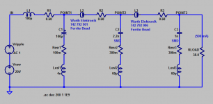
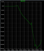
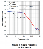
Instead of cascading four IC voltage regulators to get good ripple rejection at low frequencies, why not delete one of them and use its voltage headroom to implement RF filtering instead? Here's a quick-and-dirty demonstration, which uses up only 1 volt of headroom (500mA x 0.68R x 3), far less than a single LM317. It attenuates mains-borne RF noise quite nicely in my opinion, starting at a frequency well below the knee in the LM317's rejection curve.
_
_
Attachments
Mark Johnson - the thing is that I need some voltage drop - I have symmetric +/-17AC toroid that I would like to utilize with this project, so it is at least +/-10V dc to drop
I'm also using nice power socket with fuses and filter inside:
I have almost finished pcb project in Eagle so 4 regs are here to stay, I'm only interested in capacitor multiplier issue, is it worth it or not, this is something that I will check tomorrow - cap multiplier on protoboard and how it will impact sound quality. What will win, low noise floor vs higher supply impedance...
I'm also very curious about adding ADJ pin bypasses (C9, C12, C15 and C16 mentioned before), article in Acoustica omits them or maybe just forget to put them in schematic?
I'm also using nice power socket with fuses and filter inside:
An externally hosted image should be here but it was not working when we last tested it.
I have almost finished pcb project in Eagle so 4 regs are here to stay, I'm only interested in capacitor multiplier issue, is it worth it or not, this is something that I will check tomorrow - cap multiplier on protoboard and how it will impact sound quality. What will win, low noise floor vs higher supply impedance...
I'm also very curious about adding ADJ pin bypasses (C9, C12, C15 and C16 mentioned before), article in Acoustica omits them or maybe just forget to put them in schematic?
Last edited:
It is only the caps of the tracking pre-regulators C9 and C15 that are incorrect IMHO. These tracking pre regs are not referenced to 0v but to the voltage setting regs output. By bootstrapping the input to the regulated output these pre regs relieve the second regs of line regulation duty. The way they are connected at the moment means that the tracking pre regs will only track the output at low frequencies. All is explained, including the connections of these caps, on the Acoustica.org site.
FYI you can also improve load regulation by separating the 0 volt feed to the load into power 0v and sense 0v. To do this the only connection from the bottom of C16 and R15 should be to the 0v and the load. The power 0v connection should return from the load straight to the power source, thereby not causing common mode interference with the sense 0v line. I've done this on the regs in many amps and the resulting improvement can be heard.
John
It attenuates mains-borne RF noise quite nicely in my opinion, starting at a frequency well below the knee in the LM317's rejection curve.
Which capacitor (2.2nF) did you find with 60pH of ESL? I went over to TDK's website and checked out an X5R 2.2nF in what I figured was the smallest possible package (0201) and its SRF is about 150MHz indicating somewhat higher than 60pH ESL.
Which capacitor (2.2nF) did you find with 60pH of ESL? I went over to TDK's website and checked out an X5R 2.2nF in what I figured was the smallest possible package (0201) and its SRF is about 150MHz indicating somewhat higher than 60pH ESL.
I calculated it from a 680 pF SMD capacitor's Z-vs-f curve, then assumed a 2200pF cap would have similar inductance. Maybe I muffed the calculation.
Last edited:
FYI you can also improve load regulation by separating the 0 volt feed to the load into power 0v and sense 0v. To do this the only connection from the bottom of C16 and R15 should be to the 0v and the load. The power 0v connection should return from the load straight to the power source, thereby not causing common mode interference with the sense 0v line. I've done this on the regs in many amps and the resulting improvement can be heard.
John
Well, I'm to lazy to that, I will just put solid ground plane over everything and call it a day, It worked before, at least for me. Below is a photo of my current power module (rectification is done separately) : at the top corner there is tracking preregulator, below I've placed virtual ground based on LM313/LM337/LM336, no problems with ground plane, I don't know if its the best way to do this but what can I do - I like ground planes
An externally hosted image should be here but it was not working when we last tested it.
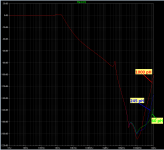
It seems to me that if you're prepared to cascade four LM317s to get excellent low frequency line rejection (4 x 61 dB = 244 dB !!), you probably also want to cascade more than one high frequency attenuator. This achieves excellent high frequency line rejection too. It therefore seems to be in the spirit of your Brute Force And Ignore The Price design style, to cascade a second RF filter after the first. You'll still get (3 x 61 dB = 183 dB) of attenuation at low frequencies from having three LM317s in series cascade, but the new RFI filter gives an extra 50dB to 180dB of attenuation at high frequencies, compared to the existing design. What's not to like?I'm also using nice power socket with fuses and filter inside:
An externally hosted image should be here but it was not working when we last tested it.
Mark Johnson - You may be right, but I can safely say that I don't know how to simulate such circuits, and capacitor multiplier is much simpler for me. It has low pass filter + multiplies capacitance, so in my understanding it attenuate high frequency and lower the noise. Using 100R and 100uF in this cap multiplier give us almost -60 db at 10kHz and it is declining.
Check this article - Simple circuits reduce regulator noise floor | EDN
Simple LM317 with ADJ bypassed + simplest capacitance multiplier at the output gives lower noise than TPS7A4700! The only problem is high output impedance.
I like brute force if it get the job done Tomorrow I will test cap multiplier consist of 100R/100uF/BC550C/BD139 and 220R to ground, if the music will not be worse, I will implement that.
An externally hosted image should be here but it was not working when we last tested it.
Check this article - Simple circuits reduce regulator noise floor | EDN
Simple LM317 with ADJ bypassed + simplest capacitance multiplier at the output gives lower noise than TPS7A4700! The only problem is high output impedance.
I like brute force if it get the job done
Tomorrow I will test cap multiplier consist of 100R/100uF/BC550C/BD139 and 220R to ground, if the music will not be worse, I will implement that.Ok, I've built cap multiplier and loaded it with resistor, works fine be me.
An externally hosted image should be here but it was not working when we last tested it.
It is only the caps of the tracking pre-regulators C9 and C15 that are incorrect IMHO. These tracking pre regs are not referenced to 0v but to the voltage setting regs output. By bootstrapping the input to the regulated output these pre regs relieve the second regs of line regulation duty. The way they are connected at the moment means that the tracking pre regs will only track the output at low frequencies. All is explained, including the connections of these caps, on the Acoustica.org site.
FYI you can also improve load regulation by separating the 0 volt feed to the load into power 0v and sense 0v. To do this the only connection from the bottom of C16 and R15 should be to the 0v and the load. The power 0v connection should return from the load straight to the power source, thereby not causing common mode interference with the sense 0v line. I've done this on the regs in many amps and the resulting improvement can be heard.
John
Sorry for the thread necro, but could you or somebody else please explain this concept further? I'm having some trouble understanding the power and sense duties, and how to implement them. I've been trying to read up on the sense part but it's not making things any clearer for me.
From the load's perspective, isn't its power source the TPR's output and return in its entirety? If so, then the bottom of C16/R15 should connect to the load's 0v, and then this entire 0v point (as far as I understand) should be referenced to the capacitor bank's return and its connection to the transformer's center tap.
How would this common setup change if trying to do what you propose?
Thanks.
Last edited:
- Status
- This old topic is closed. If you want to reopen this topic, contact a moderator using the "Report Post" button.
- Home
- Amplifiers
- Power Supplies
- LM317/337 Series Tracking Preregulator - preloading with CCS.