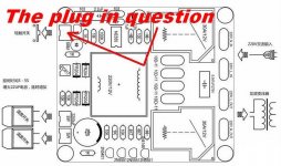
Pictured below is my Chinese soft start circuit, I purchased this assembled and I assumed plug and play but after wiring no juice, the plug/wires pictured when brushed together activate the unit and it works fine. I am not familiar with the symbol on the drawing and my Chinese is a little rusty so my question is how to wire this into the mix. I get the impression it requires a momentary switch in addition to mains on and that doesn't make a lot of sense to me. If you are familiar I would appreciate your help.
Less
Less
Attachments
This circuit has its own power supply which is on constantly. You should not use a power switch at the 115V/230V side unless you want a real 115/230V off function (Service/safety power off) for instance at the back of the device. Normally this device IS the switch to the transformer of the device you want to switch on. Please note that you MUST use a mains fuse to the 115/230V side of this device !!!!
You need a small switch to activate the relays and thus the output to the transformer. It serves like a standby/on power switch and gives the opportunity to keep 115V/230V at the back of the device and low voltage DC wiring to the front of your amplifier. That way you can buy a nice small esthetically pleasing power switch instead of a clunky 115/230V 10A rated one. No 115/230V AC wiring to the front means no possible mains hum straying in your audio electronics.
To be honest I don't see power resistors so I think this is not a soft switching device but merely a relay controlled power switch. But then again it has 2 x 30A relays so maybe there are power resistors at the bottom of the board ? It does have 2 thermal switch connectors that switch off the amplifier when either one of the channels overheats. Those are the 2 other inputs. Since it has a NE555 timer IC I think there is a delay involved too. Does not make much sense when it does not "soft switch" .....but gives a different "feel" when switching your device on. Maybe the 555 is for blinking of the LED ? Please confirm that.
*Normally soft switching means first switching the output via a resistor to lower the inrush current and then shorting that resistor to give the transformer full juice.
Last edited:
I see a 555 timer on the sheet.
So you apply mains and nothing happens. You then short the contacts and the unit operates...
Then what ? Do have to remove the mains input to reset back to off or does the momentary switch (yes that's what that symbol seems to show) turn the unit off ?
I would also as a safety precaution make sure that the momentary contacts are isolated from the mains. Is that a mains transformer in the middle powering it all ?
First experiment is to connect mains voltage and then try the on/off function by connecting the wires for a very brief time. If the device stays switched on you need a momentary switch. It it only switches on when you keep the wires connected you will need a normal on/off switch.
Keep in mind that there might be a delay involved so just wait 30 seconds after you have had the 2 wires connected together.
Work safely !
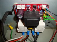
1. I see dangerous Faston connectors that are normally used in 12V car electronics. You need the ones with plastic covers for mains voltage !!!!
2. You will also need to use a plastic sheet glued to the bottom of the chassis in case one of the connectors comes off
3. You will need to mount the PCB with all 4 mounting holes and 4 stand offs with screws or nuts.
4. You do need a correctly rated mains fuse from the IEC connector to this circuit.
5. Nice to have: a plastic sheet between PCB and back cover
Keep in mind that there might be a delay involved so just wait 30 seconds after you have had the 2 wires connected together.
Work safely !
1. I see dangerous Faston connectors that are normally used in 12V car electronics. You need the ones with plastic covers for mains voltage !!!!
2. You will also need to use a plastic sheet glued to the bottom of the chassis in case one of the connectors comes off
3. You will need to mount the PCB with all 4 mounting holes and 4 stand offs with screws or nuts.
4. You do need a correctly rated mains fuse from the IEC connector to this circuit.
5. Nice to have: a plastic sheet between PCB and back cover
Last edited:
Mooly, The only supply to the unit is mains voltage with a rectifier for the dc on the board. I think I have this now. When you short the leads to turn the unit on it has to remain on for 10 seconds or so before shorting the leads again will turn it off, if you don't wait the 10 seconds it will not have any effect on it. This is what had me baffled, On but no Off. If you concur, it sounds like the mains are not switched to the soft start and the low voltage (5V) is used with a momentary switch as the on off control. Your question does it turn on and off by shorting the leads caused me to go back and explore the possibilities and discovered the 10 second dilemma. P/S If you don't mind have a look at my "NAP-140 Clone kit test & failure" post in solid state and give me your thoughts. Ian Finch gave me great advice and I do greatly appreciate respected opinions but as always I have my uncertainties in myself.
OK thanks for the reaction, it is appreciated.
BTW I think you don't have it now. Mains voltage goes to the transformer and is then rectified to DC. This PCB needs to be powered on continuously for the controls to work correctly. The small switch should be the only power on/off control. I think the chinese description says that it will switch on when the momentary switch is pushed 3 to 5 seconds.
It just occurred to me that thermal protection switches normally are "always closed" types. This could mean that you need to short the other 2 inputs when you don't use thermal protection. Just guessing....edit: I am right about this as these devices are NC devices. You will need to either connect them or short the contacts on the board.
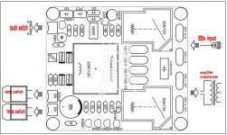
Since you are the responsive type of guy I googled some more. The 4 devices next to the transformer are PTC resistors that limit the inrush current so it really is a soft switching device. There are insulated connectors delivered with the board.
Class A Soft Start Delay Temperature Protection Board with Switch Function | eBay
The description is as follows:
4: When the amplifier board heatsink temperature exceeds 75 degrees, the board can immediately turn the power off
Source, not to the amplifier overheating. Until the temperature dropped to 75 degrees below the radiator,
Amplifier can reboot or power amplifier can not drive
BTW I think you don't have it now. Mains voltage goes to the transformer and is then rectified to DC. This PCB needs to be powered on continuously for the controls to work correctly. The small switch should be the only power on/off control. I think the chinese description says that it will switch on when the momentary switch is pushed 3 to 5 seconds.
It just occurred to me that thermal protection switches normally are "always closed" types. This could mean that you need to short the other 2 inputs when you don't use thermal protection. Just guessing....edit: I am right about this as these devices are NC devices. You will need to either connect them or short the contacts on the board.
Since you are the responsive type of guy I googled some more. The 4 devices next to the transformer are PTC resistors that limit the inrush current so it really is a soft switching device. There are insulated connectors delivered with the board.
Class A Soft Start Delay Temperature Protection Board with Switch Function | eBay
The description is as follows:
4: When the amplifier board heatsink temperature exceeds 75 degrees, the board can immediately turn the power off
Source, not to the amplifier overheating. Until the temperature dropped to 75 degrees below the radiator,
Amplifier can reboot or power amplifier can not drive
Attachments
Last edited:
So it seems this board is just an electronic on/off type of thing allowing a small momentary switch to be used. As J-P suggests, I to don't see any 'soft start' type of feature which would be a thermistor or power resistor.
Your NAP-140... something is seriously amiss for the 100 ohm to burn. Firstly the B-E junction of the output device should conduct and limit the voltage across the resistor to 0.8 (ish) as a maximum. If there were excess current available in that path then I would have thought the output device would fail short B-E anyway and save the resistor. A C-B short on TR12 would cause this as would a problem around TR10. Check if the 1N4148 has gone short. That would give a clue as to the failure mode.
You also need to check very carefully that all the devices are correct and fitted correctly. Use a bulb tester and short out the vbe multiplier from C to E (TR5) before switching on. That will force the bias current to zero.
RE: soft start
All good advice Jean-Paul and appreciated. The 30 sec. wait was the issue, I believe I have the switching issue in hand. I ran short of machine screws and misc hardware so I used enough for a mock up to form a usable layout and for testing which did not go as hoped but perseverance will prevail I hope. (see solid state)( Nap-140 test) for other rookie issues if interested.
First experiment is to connect mains voltage and then try the on/off function by connecting the wires for a very brief time. If the device stays switched on you need a momentary switch. It it only switches on when you keep the wires connected you will need a normal on/off switch.
Keep in mind that there might be a delay involved so just wait 30 seconds after you have had the 2 wires connected together.
Work safely !
1. I see dangerous Faston connectors that are normally used in 12V car electronics. You need the ones with plastic covers for mains voltage !!!!
2. You will also need to use a plastic sheet glued to the bottom of the chassis in case one of the connectors comes off
3. You will need to mount the PCB with all 4 mounting holes and 4 stand offs with screws or nuts.
4. You do need a correctly rated mains fuse from the IEC connector to this circuit.
5. Nice to have: a plastic sheet between PCB and back cover
All good advice Jean-Paul and appreciated. The 30 sec. wait was the issue, I believe I have the switching issue in hand. I ran short of machine screws and misc hardware so I used enough for a mock up to form a usable layout and for testing which did not go as hoped but perseverance will prevail I hope. (see solid state)( Nap-140 test) for other rookie issues if interested.
Are you sure you bought the 115V version ? I see there exist several versions of this board. Some are for both 115 and 230V some are explicitly not. Some use momentary switches and some newer ones need normal switches. Some have a bug that they don't start. They all look the same !
This one speaks about the need for a normal switch instead of a momentary switch.
Class A Power Amplifier Soft Start Delay Temperature Protection Board 220V New | eBay
This one speaks of a bug that is does not always start and they changed it.
Douk Class A Amplifier Power Soft Start Delay Temperature Protection Board 220V | eBay
It would be best to ask the seller for a connection diagram and an explanation what switch you need.
Last edited:
As J-P suggests, I to don't see any 'soft start' type of feature which would be a thermistor or power resistor.
Hi Mooly, the 4 x 10D-11 devices right from the small 12V transformer are thermistors/PTCs.
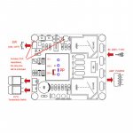
Some useful info to change the delay time:
Attachments
Last edited:
If this is of any help (DELAY)
When the two wires are shorted to turn the unit on there is a immediate click followed by the click of both relays engaging approx. 1.5 seconds later. I will voltage test this to confirm exactly what voltages and when they are delivered to the transformer and post the results.
Hi Mooly, the 4 x 10D-11 devices right from the small 12V transformer are thermistors/PTCs.
Some useful info to change the delay time:
When the two wires are shorted to turn the unit on there is a immediate click followed by the click of both relays engaging approx. 1.5 seconds later. I will voltage test this to confirm exactly what voltages and when they are delivered to the transformer and post the results.
115 volt vs 230
There is a bridge on the back side of the board to be soldered for the required voltage and this is bridged for the 115 volt. It appears that this uses the momentary switch at least it works in that fashion, the only issue is the lack of instant on off of the momentary, it needs to be on for approx 10 seconds before it will turn off That said I have can't comment on the performance as I haven't used it except to get it to function, when I am up and running I will mess with the thermal protection circuit and I will leave some feedback on the whole affair once I have some results.
Are you sure you bought the 115V version ? I see there exist several versions of this board. Some are for both 115 and 230V some are explicitly not. Some use momentary switches and some newer ones need normal switches. Some have a bug that they don't start. They all look the same !
This one speaks about the need for a normal switch instead of a momentary switch.
Class A Power Amplifier Soft Start Delay Temperature Protection Board 220V New | eBay
This one speaks of a bug that is does not always start and they changed it.
Douk Class A Amplifier Power Soft Start Delay Temperature Protection Board 220V | eBay
It would be best to ask the seller for a connection diagram and an explanation what switch you need.
There is a bridge on the back side of the board to be soldered for the required voltage and this is bridged for the 115 volt. It appears that this uses the momentary switch at least it works in that fashion, the only issue is the lack of instant on off of the momentary, it needs to be on for approx 10 seconds before it will turn off That said I have can't comment on the performance as I haven't used it except to get it to function, when I am up and running I will mess with the thermal protection circuit and I will leave some feedback on the whole affair once I have some results.
When the two wires are shorted to turn the unit on there is a immediate click followed by the click of both relays engaging approx. 1.5 seconds later. I will voltage test this to confirm exactly what voltages and when they are delivered to the transformer and post the results.
First click is the relay switching via the thermistors to limit the inrush current. Second click is the second relay bridging the thermistors. Can't be that both relays are switching on at the same time ! It can be that the first relay switches off however as the second one bridges the thermistors.
Please confirm that the unit is on 115V from the start. That you haven't used a switch before it I mean. It should be "always" connected to 115V.
* As said before: you can change the delay time.
Hi Mooly, the 4 x 10D-11 devices right from the small 12V transformer are thermistors/PTCs.
Some useful info to change the delay time:
Thanks Jean. That makes more sense now.
I have exact the same unit shown in post 1 in this thread. Its function confuse me. I have done the following test:
1. For control, I first connected the two 220 V out on the PCB to my digital voltmeter.
2. I then conneted the two 220 V in on the PCB to my mains. Without doing anything else my digital voltmeter show 230 V AC (?) No light on thered led at this point.
3. With a momentary switch connected and pulled for a short time(3 second), the red led light up. I hear the click from the relay The digital voltmeter still show 230 V AC.
4. Pulling the momentary switch for another 3 second, the red ledlight turns off. BUT THE DIGITAL VOLTMETER STILL READ 230 V AC(???)
5. So, nothing happens at the 220 V output connection when I pull the momentary switch the second time. I can hear (and feel with my fingertip) that the scond relay clicks This confuses me. I expected that at this point, the 220 V out connection should now be breaked. In pratice this means that the transformer in my amplifier will be connected to 230 V AC all the time as long as this unit is connected to my mains. I intended to use this unit in a classe A amplifier. This amplifier draw 1.8 A all the time it is connected to the mains. My conclusion is that this unit is not the right match in a classe A amplifier? Am I right?
Eivind S
Hi Mooly, the 4 x 10D-11 devices right from the small 12V transformer are thermistors/PTCs.
Some useful info to change the delay time:
I think this is correct.First click is the relay switching via the thermistors to limit the inrush current. Second click is the second relay bridging the thermistors. Can't be that both relays are switching on at the same time ! It can be that the first relay switches off however as the second one bridges the thermistors.
Please confirm that the unit is on 115V from the start. That you haven't used a switch before it I mean. It should be "always" connected to 115V.
* As said before: you can change the delay time.
The transformer is powered ON all the time.
Clicking the control switch turns on the first relay to swend power to the Live OUTPUT terminal via the soft start resistance and starts the timer delay.
After the delay has expired the second relay bypasses the added resistances.
It's the same way I have wired up my soft starts.
I also had temperature switches that turn off the first relay if the heatsink get too hot. Power goes off until the heatsink/s cool and then turns ON again after a few minutes of cooling. There is no latch. The remote turn on control avoids having to run high voltage wiring around the inside of the enclosure.
The added resistance of the Power Thermistors has almost no effect when no current is being drawn.Yes, the test I describe was without any connection to a transformer or a condenser bank.
So if I connect the unit into a amplifiers transformer and condenser bank, the 220 V out will be breaked the second time I pull the momentary switch?
Eivind S
A couple of measurements would help confirm the operation.
Disconnect all terminals, no power !
Measure the resistance between the two Neutral terminals.
Measure the resistance between the two Live terminals.
Power ON. But control OFF.
Measure the voltages at the switched Live and Neutral terminals.
Control to ON.
Do you hear the second relay clicking to ON?
Measure the voltages at the switched Live and Neutral terminals.
The time delay between the two relays clicking ON could be quite short. I use 100ms to 200ms and the dual click/delay is only just audible.
Last edited:
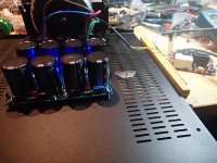
Since I for the time beeing build an Aleph J for a friend of mine, I connected the Soft Start to the V3 powerbank (no amplifiers connected). I got this measurement:
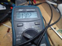
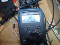
Picture 1-2:Connected to my mains, the voltage at 220V out on Soft Start rised slowly up to 130V AC, where it stopped. The blue leds on V3 started to light up very soon afte I connected the mains. At 130V AC I measured 2x12 V DC on V3.
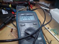
Picture 3. The momentary control ON. The red led on the Soft Start light up.
Voltage on 220V out was now 228.5 V AC(=mains voltage this evening). Voltage on V3: 25.5 V DC.
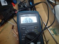
Picture 4-5: The momentary control OFF: Very fast the voltage on 220 out on Soft Start fell down to 170/60 V AC. After 3-4 minutes it is down to aprox. 130 V AC.
I have not done the measurement you asked for, Andrew(thanks for your help) since I think that connecting the Soft the way I have done, shows how it work. But again I must ask: Since the AC volt never fall down to zero, is this unit a "good idea" to connect to a classe A amplifier with a constant current about 1.8 A??
Picture 1-2:Connected to my mains, the voltage at 220V out on Soft Start rised slowly up to 130V AC, where it stopped. The blue leds on V3 started to light up very soon afte I connected the mains. At 130V AC I measured 2x12 V DC on V3.
Picture 3. The momentary control ON. The red led on the Soft Start light up.
Voltage on 220V out was now 228.5 V AC(=mains voltage this evening). Voltage on V3: 25.5 V DC.
Picture 4-5: The momentary control OFF: Very fast the voltage on 220 out on Soft Start fell down to 170/60 V AC. After 3-4 minutes it is down to aprox. 130 V AC.
I have not done the measurement you asked for, Andrew(thanks for your help) since I think that connecting the Soft the way I have done, shows how it work. But again I must ask: Since the AC volt never fall down to zero, is this unit a "good idea" to connect to a classe A amplifier with a constant current about 1.8 A??
Attachments
Last edited:
- Status
- This old topic is closed. If you want to reopen this topic, contact a moderator using the "Report Post" button.
- Home
- Amplifiers
- Power Supplies
- Soft start question