Since both me and a friend of mine have a couple of this unit, the "big question" for us is:Can it be "modded" for safe use in an amplifier, or is the bin laden the right place to put this unit?
What must be done if the unit should work properly (and safe). Changing the yellow cap has been mention. What will be a good replacement.
Nattawa, you dont like the parallel NTC thermistors. I have seen this argument in other threads here on diyAudio, that paralleling is a "bad thing" in a circuit like this. Can this problem been solved on this PCB?
It is a pity if four of this Soft Starter ends up as trash for me and my friend.
Eivind S
There is a very good reason why NTC thermistors in parallel is bad. This has to do with the NTC characteristic. Imagine several in parallel. They are not 100% identical, right? Manufacturing tolerances and the impossibility of exactly duplicating a part means that there will be differences in the cold resistance and the NTC behavior. This means that, when connected in parallel, one will have slightly lower resistance or one will have a slightly higher NTC so that it's resistance will drop faster than the others. This will cause more current to flow through that one, which will cause it's resistance to drop faster, etc. As a result more current flows through this unit, causing it to heat up even faster than the others, etc. You cannot balance the current flow with such an arrangement. While SOME current will still flow through each device one of them will get most of it and the more mismatched the devices the worse this will be.
As Andrew mentioned, it is better to put NTC resistors in series to avoid this problem.
.....the "big question" for us is: Can it be "modded" for safe use in an amplifier, or is the bin laden the right place to put this unit?
What must be done if the unit should work properly (and safe). Changing the yellow cap has been mention. What will be a good replacement.
Nattawa, you dont like the parallel NTC thermistors. I have seen this argument in other threads here on diyAudio, that paralleling is a "bad thing" in a circuit like this. Can this problem been solved on this PCB?
It is a pity if four of this Soft Starter ends up as trash for me and my friend.
Eivind S
The yellow capacitor is not a problem as it does not pass anywhere near a power capable of blowing anything.
Remove the relays and clip off the unused pin at its base, enlarge the holes for these pins on PCB to 3mm in diameter so that there is clearance around the remaining stub of the un-used pins when they are put back on the PCB.
The NTC thermistors, although two out of four actually work, could be good enough depending on how much filtering capacitance there is with the PSU. The inrush limiting circuit is designed to only take the inrush energy, not to continuously pass load current, so you may get away with them as is. The thermistor's continuous current rating is not a concern here.
The 20D-20 thermistor seems to be rated at about 100 Joule each if memory serves, two of them then make up to 200 Joule. That's good for a total of 80,000uF capacitance at 65VDC plus some spare for the initial inrush energy due to the residue magnetism of a toroid core.
If more energy handling capability is required, it is possible to make a series connection of the four thermistors by cutting the PCB copper foil and hard-wiring them. In this case, the original thermisters make a much larger initial resistance of 80 ohms (vs 20 ohms in the original design) and the 1.5 second soft start delay may not be sufficient to allow the filtering capacitors to charge up, and you may want to either tweak the 555 timer for a longer delay or to use lower resistance thermistors.
I don't know if this inrush board has a cool-off timer. It's better to have it to inhibit quick power cycling to allow time, usually 1 min or 2, for the thermistors to cool down. But if it doesn't, it's usually not a problem, just try not to repeatedly cycle the power in a short period of time. Otherwise you're heating up the thermistors, and the thermistors only works best when they are cool.
If you don't feel good about modding the ebay board, consider building my design
")
Last edited:
That capacitor is why you read unexpected voltages. Its impedance at 50/60Hz is much lower than your DMM's input impedance, so the DMM sees almost a full mains voltage when there are no other loads. Yet it is not low enough to pass the full voltage when some load is attached.
yes......this technic is seen in a lot of amps, nothing new nor strange here...
Since both me and a friend of mine have a couple of this unit, the "big question" for us is:Can it be "modded" for safe use in an amplifier, or is the bin laden the right place to put this unit?
What must be done if the unit should work properly (and safe). Changing the yellow cap has been mention. What will be a good replacement.
Nattawa, you dont like the parallel NTC thermistors. I have seen this argument in other threads here on diyAudio, that paralleling is a "bad thing" in a circuit like this. Can this problem been solved on this PCB?
It is a pity if four of this Soft Starter ends up as trash for me and my friend.
Eivind S
way i see it, the board is fine as it is....
if you are iffy about the thermal sensor bit,
i guess you can just opt to not use it...
AJT
Thanks for the input, I have started looking at spark suppression – snubber info online. It seems odd that they only included 1 capacitor rated at only 275V, not a lot of headroom, I have seen a number of people stating the cap should be 2 - 4 times the voltage.
X2 caps have a series resistor built in, if i am not mistaken.....
so arc suppression and snubbing is done at the same time...
about the 275 volts rating, i think is is enough. if you want
you can replace it with a 2kv dc/ 0.01ufd ceramic disk cap
275 ac is like 825 volts dc so a 2kv disk ceramic cap makes sense...
if i were you i will not worry too much....
this design uses two relays, the first one is
in lieu of the mechanical on off switch,
the other as a time delay relay to short out
the thermistors after a second or more of delays....
but i am sure you know this already.....
and i am also sure that once the 75 degrees C temp is exceeded,
then the 555 timer is toggled off and the two relays are turned off...
There is a very good reason why NTC thermistors in parallel is bad. This has to do with the NTC characteristic. Imagine several in parallel. They are not 100% identical, right? Manufacturing tolerances and the impossibility of exactly duplicating a part means that there will be differences in the cold resistance and the NTC behavior. This means that, when connected in parallel, one will have slightly lower resistance or one will have a slightly higher NTC so that it's resistance will drop faster than the others. This will cause more current to flow through that one, which will cause it's resistance to drop faster, etc. As a result more current flows through this unit, causing it to heat up even faster than the others, etc. You cannot balance the current flow with such an arrangement. While SOME current will still flow through each device one of them will get most of it and the more mismatched the devices the worse this will be.
i seriously doubt this.....have you done actual experiments to confirm or are you just
theorizing?
NTC's have cold resistance as initial condition,
now as current passes, they heat up and resistance drops to below an ohm....
i have seen NTC's used in millions of ATX power supplies around the globe,
no relay was ever used to short them out.....why do you think that is?
i have repaired thousands of ATX psus in a span of over 10 years,
and only once did i see one NTC fail,
but before it did, there was a loud bang on the computer as it booted up,
and yet the computer still went into windows, until one day it just gave up
and failed as an open circuit....
but why worry about parts that will see action for just a second or two
and then get shorted out?
X rated capacitors are just capacitors.X2 caps have a series resistor built in, if i am not mistaken.....
so arc suppression and snubbing is done at the same time...
about the 275 volts rating, i think is is enough. if you want
you can replace it with a 2kv dc/ 0.01ufd ceramic disk cap
275 ac is like 825 volts dc so a 2kv disk ceramic cap makes sense...
if i were you i will not worry too much....
Interference suppressors are a combination of resistor and capacitor built into one two leg package.
Doubt his description as much as you like. Just don't try to pass on any non science.i seriously doubt this.................
CharlieLaub's post61 is substantially correct.
a few that start with a low cold resistance may drop to below an ohm. Most will never get as low as an ohm. That's the first "non science" myth you are trying to promote.now as current passes, they heat up and resistance drops to below an ohm....
I doubt you have ever "seen" millions of NTCs that were used in SMPS. Exaggeration does not promote confidence in anything you may want to post.i have seen NTC's used in millions of ATX power supplies around the globe,
Could it be penny pinching? Or because the manufacturer thought the SMPS worked better by leaving the Power Thermistor in circuit.no relay was ever used to short them out.....why do you think that is?
Last edited:
Could it be penny pinching? Or because the manufacturer thought the SMPS worked better by leaving the Power Thermistor in circuit.
whatever the reason, atx psu never used a relay to short out the NTC's because it is not needed....period....
that the NTC's need to be shorted out is an invention of the audiophile crowd....
show me any DIN or UL engineering document that says NTC's needed to be shorted out...
resistance of NTC's go below an ohm.....see page 8 of this document....http://www.murata.com/~/media/webrenewal/support/library/catalog/products/thermistor/ntc/r44e.ashx
Doubt his description as much as you like. Just don't try to pass on any non science.
CharlieLaub's post61 is substantially correct.
quite the contrary, a careful investigation is needed to verify claims,
otherwise they remain as mere claims....where is the data?
my take is that those NTC's can be shorted out if desired,
but that is not the norm or mandatory requirement....
I doubt you have ever "seen" millions of NTCs that were used in SMPS. Exaggeration does not promote confidence in anything you may want to post.
so where is your proof that those NTC's need shorting out?
a few that start with a low cold resistance may drop to below an ohm. Most will never get as low as an ohm. That's the first "non science" myth you are trying to promote.
so where is your document that proves this? or are we just going to take your word
for it as if it was gospel truth?
Hi
AndrewT
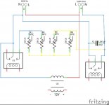
your diagram can't be right.
Uh oh..... I drew the circuit because what I am seeing on the board is not the same as the schematic posted by AJT. I have gone over it again and as far as I can see it is correct, what are you seeing that isn’t correct?
I am going to try a replacement cap to see if there is a problem with the original item but I am thinking about increasing the voltage because the house voltage is around 230 to 241V so I am concerned the original parts rating of 275V doesn’t leave room for much movement.
Liliya
Taking the capacitor out certainly solved the problem on my board, that said, I haven’t tested it beyond powering it without the output connected and again with the toroidal transformer connected and measuring the 220V out. Power on and switch off, without any load I saw about 13V and with load connected I saw 0V.
The soldering on my board was poor, there were lots of holes and some pads had very little solder. I don’t think the solder they used is very good, it doesn’t flow well and for some reason it gets air bubbles a lot. I ended up removing and renewing the solder on each joint. On a positive note, their solder means it is fairly easy to remove parts from the board.
Nattawa
The 110V-ish reading was with both the toroidal transformer on its own and with a 5V LDO voltage regulator board connected. One of the secondaries is normally 13V, since I was seeing 7.1V I thought I would give the regulator a try. I measured a steady 5V DC on its output, the board has a rectifier, 2 capacitors and an LED, I didn’t connect anything to the regulator.
I think I will take your suggestion to remove the relays and cut the redundant pin off.
AJT
Your description of of the boards operation (post 66) is inline with what I have seen.
The only thing I can add it there isn’t a restart delay. If the unit is switched off it can be restarted immediately. The unit switches off when the 75 degrees C temp circuit is closed (the temp sensors are Normally Open) the unit can be restarted as soon as the temp circuit opens again.
Regards
AndrewT
your diagram can't be right.
Uh oh..... I drew the circuit because what I am seeing on the board is not the same as the schematic posted by AJT. I have gone over it again and as far as I can see it is correct, what are you seeing that isn’t correct?
I am going to try a replacement cap to see if there is a problem with the original item but I am thinking about increasing the voltage because the house voltage is around 230 to 241V so I am concerned the original parts rating of 275V doesn’t leave room for much movement.
Liliya
Taking the capacitor out certainly solved the problem on my board, that said, I haven’t tested it beyond powering it without the output connected and again with the toroidal transformer connected and measuring the 220V out. Power on and switch off, without any load I saw about 13V and with load connected I saw 0V.
The soldering on my board was poor, there were lots of holes and some pads had very little solder. I don’t think the solder they used is very good, it doesn’t flow well and for some reason it gets air bubbles a lot. I ended up removing and renewing the solder on each joint. On a positive note, their solder means it is fairly easy to remove parts from the board.
Nattawa
The 110V-ish reading was with both the toroidal transformer on its own and with a 5V LDO voltage regulator board connected. One of the secondaries is normally 13V, since I was seeing 7.1V I thought I would give the regulator a try. I measured a steady 5V DC on its output, the board has a rectifier, 2 capacitors and an LED, I didn’t connect anything to the regulator.
I think I will take your suggestion to remove the relays and cut the redundant pin off.
AJT
Your description of of the boards operation (post 66) is inline with what I have seen.
The only thing I can add it there isn’t a restart delay. If the unit is switched off it can be restarted immediately. The unit switches off when the 75 degrees C temp circuit is closed (the temp sensors are Normally Open) the unit can be restarted as soon as the temp circuit opens again.
Regards
Attachments
the harmonised voltage is from 216Vac to 253Vac for the whole of the EU.Hi
AndrewT
your diagram can't be right.
Uh oh..... I drew the circuit because what I am seeing on the board is not the same as the schematic posted by AJT. I have gone over it again and as far as I can see it is correct, what are you seeing that isn’t correct?
I am going to try a replacement cap to see if there is a problem with the original item but I am thinking about increasing the voltage because the house voltage is around 230 to 241V so I am concerned the original parts rating of 275V doesn’t leave room for much movement.....................
275Vac is the standard X2 rated capacitor for use on the harmonised supply.
They do make an X1 rated capacitor for use on the three phase 400Vac supply, but that is not what YOU need for an ordinary single phase domestic supply.
Use the 275Vac X2 rated capacitor. It is designed to fail safe for upto 253Vac. And for the very short periods that the harmonised supply is allowed to exceed 253Vac.
Your new diagram in post74 looks better. Can't you see that post55 is different?
Look at the Live lead. It supplies only the little transformer, nothing else. It can't be right.
Last edited:
Many moons ago I worked in a British electro mechanical telephone exchange. All the mechanical selectors or "motors" that switches between the contacts had these ceramic coated caps in series with resistors that were wired in parrallel with the contacts of the motor. So the motor switches through it 's own contacts. That was called spark suppression to protect the contacts. I think they called it something like an admite ? They worked from 50Vdc but the back emf across those contacts has a hell of a shock !! Where are the good old day's !X rated capacitors are just capacitors.
Interference suppressors are a combination of resistor and capacitor built into one two leg package.
AJT
Your description of of the boards operation (post 66) is inline with what I have seen.
The only thing I can add it there isn’t a restart delay. If the unit is switched off it can be restarted immediately. The unit switches off when the 75 degrees C temp circuit is closed (the temp sensors are Normally Open) the unit can be restarted as soon as the temp circuit opens again.
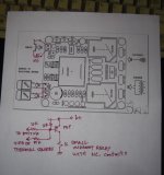
we are left with no other option but to use it as it is....unless
a relay contact in series with the start switch, normally closed,
that opens when the thermal switches are activated so that
pushing the start switch will not turn on the psu until the heat
issue dies down, this will add complexity but is doable....
i have attached a simple mod to make this controller not
restarting right after shutdown due to heat.....
another way can be designed to inhibit the start switch
for some time, another added complexity but still doable...
if we can imagine it, we can do it...
Attachments
My issue had to do with grounding. I had purposed the question earlier, does the power supply and the amplifier circuitry all require earth grounding, I never received a clear yes or no on this question and may have missed the answer somewhere. For future reference for anyone reading this the answer is yes all negative circuitry requires chassis grounding/earth grounding. This solved completely all of my issues. I apologize for lack of response but I was unable to as I have been very ill. Thanks for your help.
Dave
Dave
- Status
- This old topic is closed. If you want to reopen this topic, contact a moderator using the "Report Post" button.
- Home
- Amplifiers
- Power Supplies
- Soft start question