I'm working on a SE KT88 amplifier design and wanted to get the groups thoughts on splitting the B+ feed after the first cap (following the 5U4G or similar) into a choke per channel.
I've seen some high end designs that deploy such a topology but its typically a full LC filter followed by two additional LC filters, one per channel.
My main reason for considering this approach is to keep the choke size to 100ma per channel thus smaller in size and being able to fit them under the chassis. I'm trying to avoid an above chassis choke, more for cosmetics of the design.
I know it would be a slightly more complex design but that's acceptable to me.
Thoughts? Pros/Cons?
Thanks,
Mark
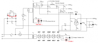
You mean something like this (attached)?
For the Vixen, I split the filtering of the positive rail, as shown in the schemo, since this is a passive filter. I didn't split the negative rail since the current demand is very much lower, and this includes an active decoupler that has a much lower impedance.
There really is no need for common LC filtering followed by separate LC filters, at least not these days since high value, high voltage, capacitors are now available. 8H and 220uF gives a cutoff of about 4.0Hz (4.91 octaves) and more than enough ripple suppression. Not like back in "the day" when 20uF was about as large a capacitor you could find, so you needed to cascade LC filters to reject that AC ripple.
I considered doing away with LC filtering altogether, but since the PTX is a Hammond "Classic", not too sure how it would appreciate the much larger isurge of Si diodes operating into huge capacitors. Even so, the 47uF reservoir capacitor would bust the Isurge spec of the 5U4GB.
Attachments

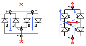
Before someone make the same mistake, little adjustements
Mona
That's not a mistake, and those "adjustments" aren't necessary. That schemo is exactly like how I built it. You definitely don't need those extra diodes with the LEDs: they're redundant. Also, don't screw around with the ground breaker either. The connection shown parallels two diodes in "69" fashion. Breaking that connection as shown cuts the current handling capacity in half.
Agree with not disturbing the grounding.
The reverse diode on the LED is generally good practice when it is fed from AC. Most LEDs have reverse breakdown voltages in the region of just over 5 volts. If fed from an AC with a limiting resistor they will work, but they may degrade over time and fail later. The reverse diode limits the reverse voltage on the LED to less than a volt, at the price of increased dissipation in the resistor.
If the AC voltage is low, the extra diode can be omitted, but I always put one in. It costs almost nothing, and saves the LED. Note that the diode can be any low voltage type - it only sees the LED forward voltage as its reverse voltage.
This is generally a better solution than a series diode, because the voltages are controlled. In the series case, the additional diode and LED share the reverse voltage but not in a controlled way and so the LED can still be stressed.
The way you do it is just two diodes back to back, no need for a bridge.That's not a mistake, and those "adjustments" aren't necessary. That schemo is exactly like how I built it. You definitely don't need those extra diodes with the LEDs: they're redundant. Also, don't screw around with the ground breaker either. The connection shown parallels two diodes in "69" fashion. Breaking that connection as shown cuts the current handling capacity in half.
Like I changed it gives two diodes in series back to back.That gives a liberty of 1.2V before there is a ground current, in your version it's only 0.6V.
Mona
Attachments
Agree with not disturbing the grounding.
The reverse diode on the LED is generally good practice when it is fed from AC. Most LEDs have reverse breakdown voltages in the region of just over 5 volts. If fed from an AC with a limiting resistor they will work, but they may degrade over time and fail later..
"Over time" means ten years now (I completed the Vixen in Dec, '05) of almost daily use for a couple hours or more, and "later" has yet to occur.
The way you do it is just two diodes back to back, no need for a bridge.
Like I changed it gives two diodes in series back to back.That gives a liberty of 1.2V before there is a ground current, in your version it's only 0.6V.
Mona
You're still cutting the current carrying capability in half, and that's what's important: in the case of a catastrophic failure that makes the chassis live, you want the fuse to poof before the diode bridge. Low PRV, high current integrated bridges aren't that expensive, and are cheap insurance against a dangerously live chassis.
- Status
- This old topic is closed. If you want to reopen this topic, contact a moderator using the "Report Post" button.
- Home
- Amplifiers
- Power Supplies
- Splitting Power Supply Choke Question