He put it out as a "holiday" present on the blog:
Walt's Blog 2014 | Walt Jung's 2014 Blog and Info Archive
Walt's Blog 2014 | Walt Jung's 2014 Blog and Info Archive
Last edited:
")
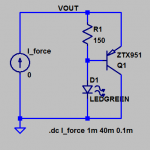
Since there's no NFB, it appears to me that the output impedance (dVout/dIout) when running 5mA, will be a little more than 5 ohms (?). The LM329's Zout is 0.6 ohms typical, and the TL431's Zout is 0.2 ohms typical. I'll slap together a SPICE trial of Walt's goody and see if it disagrees with my 5 ohm estimate.
I couldn't find a SPICE model of that Lite-On green LED, so this simulation may not accurately reflect a real GLED431 in a real circuit. Instead I used the green LED model from Bob Cordell's website. I did find a model of the Zetex PNP device that Walt specified.
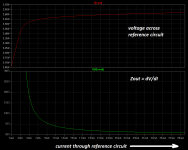
The first attached figure shows the simulation schematic: it forces a current into the reference circuit, and measures the reference voltage. I stepped current from 1mA to 40mA, giving a healthy cushion on either side of Walt's recommend 5mA operating point.
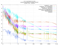
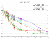
The second figure shows the LTSPICE results. The reference voltage flattens out and becomes approx. constant when the current exceeds about 7mA or so (red curve, top panel). The incremental output impedance dV/dI is pretty high at low currents. Then as current increases, the "re" term from the transistor (1/gm) diminishes, and eventually the impedance flattens out to something in the neighborhood of (R1 || Zled)/Beta.
_
The first attached figure shows the simulation schematic: it forces a current into the reference circuit, and measures the reference voltage. I stepped current from 1mA to 40mA, giving a healthy cushion on either side of Walt's recommend 5mA operating point.
The second figure shows the LTSPICE results. The reference voltage flattens out and becomes approx. constant when the current exceeds about 7mA or so (red curve, top panel). The incremental output impedance dV/dI is pretty high at low currents. Then as current increases, the "re" term from the transistor (1/gm) diminishes, and eventually the impedance flattens out to something in the neighborhood of (R1 || Zled)/Beta.
_
Attachments
I couldn't find a SPICE model of that Lite-On green LED, so this simulation may not accurately reflect a real GLED431 in a real circuit. Instead I used the green LED model from Bob Cordell's website. I did find a model of the Zetex PNP device that Walt specified.
The first attached figure shows the simulation schematic: it forces a current into the reference circuit, and measures the reference voltage. I stepped current from 1mA to 40mA, giving a healthy cushion on either side of Walt's recommend 5mA operating point.
The second figure shows the LTSPICE results. The reference voltage flattens out and becomes approx. constant when the current exceeds about 7mA or so (red curve, top panel). The incremental output impedance dV/dI is pretty high at low currents. Then as current increases, the "re" term from the transistor (1/gm) diminishes, and eventually the impedance flattens out to something in the neighborhood of (R1 || Zled)/Beta.
_
Nice Mark, so your estimate was not too far off. I think I'll pass - there's much, much better ones out there even simple devices like the '329 and the '431. Thanks for the checking.
Jan
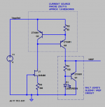
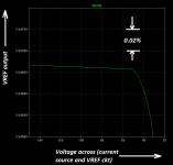
Walt might have been expecting that users would drive his GLED431 with a very high impedance (like a constant current source), in which case the Zout of the GLED431 is not so important. So I ran a simulation of that case, shown below. Bias current in the simulated GLED431 is 7mA. The output VREF remains constant despite rather large changes in the applied voltage.
_
_
Attachments
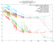
Methinks the wording "behaves as a very low noise Zener" does no justice to Zeners.
An NXP BZX84C2V7 or 3V3 is 6 dB above 1nV/sqrt(Hz) or 2nV/sqrtHz, just pick it
from the tape. And the 1/f corner is at 10 Hz.
On the plot you can see how they get worse step by step when the voltage is increased.
Also, I do not really like the gain-up circuit to 5V; it doubles the noise voltage whereas
two cells in series would deteriorate only by a factor of 1.414, and they would be cheaper.
The LT6200 costs some $4 and is has a high 1/f corner.
The regulators have been measured in their typical application circuit with
generous decoupling of the reference where possible.
The LT3042 wants its 4.7uF output capacitor to have just that value. Departing
in either direction creates noise peaks at high frequencies, but still with an absolute
value the others can only dream about.
That sensitivity is also seen on the LT6655, which is a band gap but noise-wise as
good as the usual precision zeners. The app note circuit with the external npn
seems to hurt its perfomance, I need another measuring session for it.
The HLMP-6000 was proposed by someone in the Blowtorch thread.
The LEDs (and Zeners) were powered by a 1 or 2K wire resistor from 10 NiMH cells.
The plot of the 47 Ohm resistor instead of a LED shows that there comes no
noise from the supply.
The preamp has 220pV/sqrt Hz with 20 ADA4898 opamps averaged.
I have described it in < http://www.hoffmann-hochfrequenz.de/downloads/downloads.html >
An Agilent 89441A did the FFTs decade by decade; I have written a control
program for Linux that controls it over the network, collects the data and
plots it via gnuplot.
regards, Gerhard
Attachments
Last edited:
increase the number of LEDs....................Also, I do not really like the gain-up circuit to 5V; it doubles the noise voltage whereas
two cells in series would deteriorate only by a factor of 1.414, and they would be cheaper...............
Vout = Vbe+Vfled
I did this as an experiment some years ago for a 3V3 supply.
One can add any mix of schottky/silicon/irled/green/red/yellowled to coarse tune the output voltage and then set the current to fine tune the output voltage.
Last edited:
I'm highly interested in this voltage reference. Is there any particular reason to use ZTX951? How about BC560 low noise PNP?
Yes, the BC560 is much higher noise than the ZTX951. See AoE, 3rd edition, Table 8.1a. Per H/H, rbb for a BC550C is 170ohm, while ZTX851 is at 1.67ohms. The PNP counterparts are typically lower in noise. The ZTX851/951 pair seems to be the best there is right now (still in production / conventional packaging).
See AoE, 3rd edition, Table 8.1a. Per H/H, rbb for a BC550C is 170ohm, while ZTX851 is at 1.67ohms.
A hearty thank you, Rax! I thought I wasn't interested in upgrading from the 2nd Edition to the 3rd until I saw your post. 10 minutes after reading your message I ordered the book from Amazon with 2 day shipping and am eager to read it carefully. Curious to see how well or how poorly my most recent order (500 pieces!) compares: I bought 2SC6043 / 2SA2127. From the totally awesome Sanyo "MBIT" process having fT = 420 MHz and very low Vcesat.
There has been a lot of unsupported guessing / self important pontificating, here and elsewhere, that when selecting transistors, low noise is perfectly correlated with low Rbb', AND furthermore, low Rbb' is highly (not perfectly) correlated with extremely low VCEsat and extremely high ratios of (Ic/Cce). Your data informs that narrative. Well done and thank you.
Mark Johnson
Yes, the BC560 is much higher noise than the ZTX951. See AoE, 3rd edition, Table 8.1a. Per H/H, rbb for a BC550C is 170ohm, while ZTX851 is at 1.67ohms. The PNP counterparts are typically lower in noise. The ZTX851/951 pair seems to be the best there is right now (still in production / conventional packaging).
Thanks for the explanation. I will definitely try the ZTX951 first.
That's impressive, so I looked at the datasheet.Sanyo "MBIT" process having fT = 420 MHz
The 420MHz for fT is the peak when Ie ~200mA to 300mA.
It is down to ~200MHz when Ie is around 23mA. & 100MHz @ 10mA of Ie.
That in my book would make it a 200MHz device when using similar parameter definitions from other comparable devices.
I note also the high Cob of 16pF @ 10Vce. That too points to the 420MHz for fT, as not being a useful value for design.
Last edited:
I believe they are talking about "The Art of Electronics" by Horowitz/Hill... Please do correct if my assumption is wrong.
-A.Kiuas
Sorry for my extreme abbreviating there, indeed, that is the source.
- Status
- This old topic is closed. If you want to reopen this topic, contact a moderator using the "Report Post" button.
- Home
- Amplifiers
- Power Supplies
- Mr. Jung's ultra-low noise VREF - the GLED431