I think you are right about the dragging down of Vref through R38. R38=100k and Vref at D4 sits at 6.8V - still a little low as the drop across R36 is still about 0.2V. So Vref circuit ok but output sitting at 15.17V (+ if I run just that half of the circuit and, of course, -ve if I run both). (Vout of both pre-regs is 16V.)
Attachments
I need to pick this up in the morning, but I did take another quick look. I see that I am not getting the same voltage drop across R19 (0.276V) and R22 (0.166V) even though they measure the same resistance, 34.8R. I am also dropping 5.61V across R20 which also measures true at 453R.
A current mirror circuit that fails to mirror currents, is indeed suspicious. Maybe the components inside the mirror are bad. Or maybe the external environment is forcing the mirror to operate in a bias configuration outside its design limits.
Fortunately you've got a known-good copy of the same circuit, right there on your PCB. So you can compare the VCEs and VBEs and ICEs of the individual transistors, to see whether they are operating outside the expected and legal "forward active mode".
Oh and just to eliminate one source of possible doubt, you can consider removing 330uF capacitors C11 and C12 from the PCB. Their purpose is to reduce sensitivity to AC disturbances, while you are solving a DC biasing error. If you remove these caps from the board you immediately KNOW they are not leaking, you KNOW they are not shorted.
If good is left and suspicious is right---
_
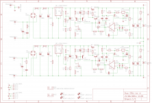
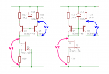
Attachments
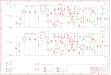
Of course, I just couldn't put it down... Replacing Q6 didn't solve anything. I checked all the relevant voltages between the two regs. See attached. There's a problem with the level shift, but replacing the SPX431 didn't solve it. So I have now replaced Q4, Q6, Z2 plus Q10 for good measure. That only leaves Q2 and Q8 as original active parts. C12 removed makes no difference. If Q8 were toast I would expect 16V at the output rather than 15.16 (and I wouldn't expect to see a problem with the level shift). All resistors measure as they should. Circuit trace continuity would seem correct.
I would have thought the issue is the level shift but I'm surprised replacing Z2 didn't help. Perhaps I have several duds or it is being damaged when soldered. Perhaps replacing it temporarily with a simple resistor would help in isolating the issue. But time for some sleep now...
I would have thought the issue is the level shift but I'm surprised replacing Z2 didn't help. Perhaps I have several duds or it is being damaged when soldered. Perhaps replacing it temporarily with a simple resistor would help in isolating the issue. But time for some sleep now...
Attachments
Perhaps replacing it temporarily with a simple resistor would help in isolating the issue.
A dumb idea. That would be a negative shift!
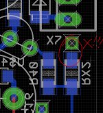
It's amazing what can happen when you leave something alone for a day or so. Tonight I couldn't get to sleep and so I popped back to this after a day or so's break from it. Within about 15 seconds I found the problem. I said to myself "well if Vref is good and I can't find a problem with the current source/mirror and level shift part of the circuit, let's at least double check the other input into the op amp." Then as I looked for RX2 to be ready to probe it I see a via with nothing attached to it. Plain as day as if it were blinking neon. A quick check of the Eagle file and the air wire, an uncompleted trace, is confirmed. Doof! Luckily it is easily bridged with solder and the correct output voltage is achieved.
Tomorrow I will try to find the time to revisit the points made by Mark in post 199.
Tomorrow I will try to find the time to revisit the points made by Mark in post 199.
Attachments
Last edited:
Ouch. Is there a "Design Rule Check" button with an "Unconnected Nets" tab in Eagle?
I selected KiCad because it's free and because it lets me build arbitrarily large boards with arbitrarily many layers, for free. One of KiCad's idiosyncrasies is that it demands the layout must exactly match the schematic, EXACTLY match. So KiCad will scream its bloody head off when you run DRC / Unconnected Nets, if the schematic says pin P connects to net N but that connection is not present in layout. You can't make KiCad stop screaming. Sometimes this is inconvenient, as when you want to use a jumper wire but are forced to go back and put it in the schematic before you can lay it out on the PCB. Other times it saves your butt_ when it shows you an error your eyes didn't notice. {The above discusses "opens" ; KiCad screams just as loudly when it finds "shorts" too.}
It implicitly assumes the schematic is perfect and golden. Which is silly because fallible humans can make just as many mistakes creating schematics as they make creating layout. So savvy users do whatever they can to protect themselves from human-caused schematic errors. The gold standard is to netlist the KiCad schematic straight to ascii text SPICE format and simulate the actual board level schematic directly, in SPICE. If it simulates good, it is good. (Or as good as the stimulus you apply in simulation). But sometimes that's difficult / impossible.
Then there are techniques, heuristics, and tricks. Things experienced people do, that would have prevented / illuminated their previous mistakes. One trick I have learned to do, is to label every circuit node on the schematic with a human readable name. FETGATE, PBIAS, FBAK, etc. Sometimes when I feel whimsical, RALPH, ALICE, FRED, WILMA. Then if I see "net_0001" on a netlist or on the layout, I know it's a schematic error that needs to be fixed. Saves my butt_.
Hi. I started with Eagle and have been reluctant to learn another software suite. I started with the freeware version and ended up having to pay a small amount for the hobby version when my boards exceeded the allowable size of the freeware version.
I went back and checked ERC and DRC on the file. Neither throw out an error for the 'airwire'. ERC even states the board and schematic are consistent with the airwire outstanding. But I have noticed now that the 'ratsnest' tool does tell me if I have airwires. I still had another even after fixing this one. Unfortunately, unlike with the DRC or ERC it doesn't tell me where the airwires are which is rather annoying (perhaps there is some 'hidden' trick to help here - there certainly isn't an obvious one). I finally found it after about 10 minutes of searching the board in high zoom. Trace from R39 to via to GND. Fortunately the trace made it to the edge of the via and the error was merely that I hadn't (somehow) connected the trace to the centre of the via (no idea how not give the way Eagle routing works). I may remove a little of the mask on the end of the trace and via and glob it with solder for good measure.
I went back and checked ERC and DRC on the file. Neither throw out an error for the 'airwire'. ERC even states the board and schematic are consistent with the airwire outstanding. But I have noticed now that the 'ratsnest' tool does tell me if I have airwires. I still had another even after fixing this one. Unfortunately, unlike with the DRC or ERC it doesn't tell me where the airwires are which is rather annoying (perhaps there is some 'hidden' trick to help here - there certainly isn't an obvious one). I finally found it after about 10 minutes of searching the board in high zoom. Trace from R39 to via to GND. Fortunately the trace made it to the edge of the via and the error was merely that I hadn't (somehow) connected the trace to the centre of the via (no idea how not give the way Eagle routing works). I may remove a little of the mask on the end of the trace and via and glob it with solder for good measure.
Last edited:
Yikes that's annoying. Ever the optimist, I imagine there must be at least one chat forum or YahooGroups or DIYA thread, where Eagle users and power-users hang out. Like what exists in the LTSPICE group. I gotta believe that other Eagle customers have run into this deficiency, and either filed bug-reports or at least cooked up some clever workarounds or best practices or something, that improves the quality of life for Eagle users, and boosts their probability of success. Maybe somebody can give you a Eureka, so you won't have to laboriously scan the entire board manually, at high mag, sniffing for tiny whiffs of faulty aroma.
Yes there is an Eagle forum I can check.
I'm missing something fundamental here (and I am likely going to screw up my terminology here as well)...
I thought the 'speed' of the regulator depended heavily on the pass transistor's transconductance, gm, or how quickly Ic can be varied by changes in Vbe. A faster op amp driving a faster pass transistor is a better regulator (assuming stability and other factors remaining the same). We had hoped - when led by the device's stock LTspice model - that the IPP037N06L3 Mosfet was faster than a BJT but were disappointed to find the model did not reflect reality. All BJT have the same transconductance.
This circuit is virtually the same as the NMOS-based circuit except, as you note, the pass transistor is a PNP BJT driven by a NPN BJT in Sziklai formation. The op amp, output caps etc are the same. So we have replaced a lower gm N-MOSFET with higher gm BJTs. Surely the regulator ought to be faster to react to changes in Vout or is it just the compound nature of the Sziklai pass transistor configuration which introduces potential sluggishness?
3. Simulation may be able to tell you how "slow to react" the two designs "should" be. Remember that the BJT Sziklai output stage uses a common emitter PNP amplifier stage (Q7 in post #175) to deliver the majority of the output current, which might or might not be slower than a common source NMOS follower stage.
I'm missing something fundamental here (and I am likely going to screw up my terminology here as well)...
I thought the 'speed' of the regulator depended heavily on the pass transistor's transconductance, gm, or how quickly Ic can be varied by changes in Vbe. A faster op amp driving a faster pass transistor is a better regulator (assuming stability and other factors remaining the same). We had hoped - when led by the device's stock LTspice model - that the IPP037N06L3 Mosfet was faster than a BJT but were disappointed to find the model did not reflect reality. All BJT have the same transconductance.
This circuit is virtually the same as the NMOS-based circuit except, as you note, the pass transistor is a PNP BJT driven by a NPN BJT in Sziklai formation. The op amp, output caps etc are the same. So we have replaced a lower gm N-MOSFET with higher gm BJTs. Surely the regulator ought to be faster to react to changes in Vout or is it just the compound nature of the Sziklai pass transistor configuration which introduces potential sluggishness?
Last edited:
Electrical Engineering is a topic that requires 4 years of university to learn, and arguably, several more years of practice to really understand. I do not agree with some authors who pretend their circuit design books which deliberately omit algebra, calculus, and Laplace Transforms, are good ways for non-EEs to absorb a few idioms of circuit designs. Nor do I wish to offer myself as a tutor who will patiently explain any and all EE topics, immediately upon request, at no charge.
The unspoken and uncomfortable truth is that "gm" is the first partial derivative of the Ids-vs-Vgs curve (MOSFET) or the first partial derivative of the Ice-vs-Vce curve (bipolar). It's calculus I'm afraid. You apply "gm" to a small signal equivalent circuit using the hybrid pi model (model: a simplified mathematical description of a complex physical system) and you write and solve the node equations of this equivalent circuit in the Laplace (complex frequency) domain. Sorry but it really is math, and that math really is advanced, despite what oversimplifiers may pretend in the sixth editions of their books.
I imagine you may be confused by the fact that when mathematically agile people work their way through the calculus / Laplace / analysis, they find that the (open loop) output impedance of a source follower is closely approximated by (1/gm). Similarly the output impedance of an emitter follower is closely approximated by (1/gm). Perhaps you internalized this in a general way: high_gm is good, low_gm is not as good.
These same mathematically agile people find that the "speed" of a feedback control system, responding to a disturbance or perturbation of some kind, is dependent upon several additional circuit properties besides the gm of the output stage.
I find that I prefer Bob Cordell's book's approach: Teach the actual hybrid pi model of transistors, show what gm is and why it works that way, show how to calculate it by hand. Show small signal equivalent circuit models of entire power amplifiers and show how to analyze them by hand. Then suggest that LTSPICE simulation is almost as good, and one thousand times quicker, and ten thousand times easier.
So if you want to perform comparative analysis upon the "speed" of two regulators, I think you will first need to decide what you mean by "speed" and how to measure it. Then either do the small signal equivalent circuit analysis of both, or run simulations of both. Asking someone else to do either of these for you, may or may not yield immediate results.
That's fair. I find that I can work through materials such as those in Art of Electronics okay (sometimes easily and at other times with much more difficulty) but then still struggle to apply that newly gained 'knowledge' to a more conceptual or true understanding of the 'macro'. In this instance I think of 'speed' of the regulator as how quickly the feedback control system (a sense versus reference network and an op amp to drive change) can return the system to a level of balance. And, yes, when all components (ignoring for now the pre-regulator introduced here) are basically the same except the pass/control device I do think of such speed as being determined by the ability of control device to react to that which drives it - in this case Vgs or Vbe, as the case may be, supplied by the comparator. So a steeper Ic vs Vbe curve ought to yield a faster control system (ceteris paribus). And a steeper Ic vs Vbe curve = greater gm, no? Clearly it's more complex of I have something wrong. I'll keep at it.
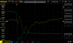
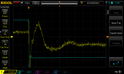
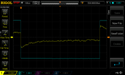
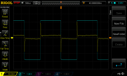
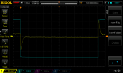
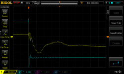
Here's a series of scope shots using 16 sample averaging, the other (-ve) side of the regulator, probing the output connector.
It would seem the unexpectedly high output impedance is prevalent on both sides of the board.
It would seem the unexpectedly high output impedance is prevalent on both sides of the board.
Attachments
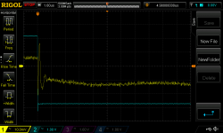
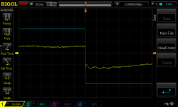

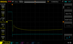
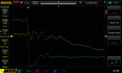
I also probed the pre-regulator's output capacitor terminals. (note different vertical scale)
Attachments
Last edited:
Yes I had noted the output impedance spec in the LM2941 data sheet also. At this stage I can only presume I have a bad bunch of LM2941 because I don't see a significant resistance in series with the output pin of the LM2941. When I saw the above measurement results I was contemplating testing a version which bypassed the pre-reg.
Other possibilities might include (a) your measuring instruments are less accurate than TI's; (b) you are not measuring the same thing under the same conditions as TI; (c) you have not connected your instruments to the D.U.T. correctly; (d) TI's datasheet is full of lies; (e) you are measuring a freak, out-of-spec, part; and so on.
Re: "speed"
Among the several possible ways to examine this in LTSPICE simulation, I think one exercise that might produce more light than heat, might be to run the open loop AC analysis simulations of both regulators and compare their unity gain bandwidths. UGB == the frequency at which open loop gain falls to and below 0dB (unity). This frequency depends on many factors, including the microscopic details of Rstability, Cstability, output transistor intrinsic capacitances Cgs, Cgd, Cbe, Cbc, base stopper resistance, gate stopper resistance, impedance ratio between opamp output and (level shifter + output xitor input), and no doubt many more.
But don't do it if you don't believe in it or if you don't quite understand it. Use your own personal definition of "speed" that you do understand and that you do know how to measure. The doubt belongs to you and so does its resolution.
- Status
- This old topic is closed. If you want to reopen this topic, contact a moderator using the "Report Post" button.
- Home
- Amplifiers
- Power Supplies
- Thermal considerations for Fairchild SDIP bridge rectifiers