Hi peeps my power tranny blew a little while ago I got a new one wound
With no winding centre taps as I was installing it with artificial centre taps on the pre and power tubes I put one on the rectifier tube filiment but thought I'd better ask if this is possible before I power up I'm not keen to let the smoke out of anything else
With no winding centre taps as I was installing it with artificial centre taps on the pre and power tubes I put one on the rectifier tube filiment but thought I'd better ask if this is possible before I power up I'm not keen to let the smoke out of anything else
Attachments
To be clear my old tranny had winding centre taps but my new one doesn't any advice on this matter would be great thancs
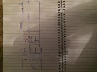
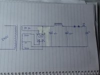
The schematic contains some (dangerous) mistakes.
The rectifier heater pins (2 and 8) voltage is about +400V! If you put between this points and the negative point 100R resistors, the resistor's current will be 4A!
Try hibrid rectifier.
Attachments
Hi peeps my power tranny blew a little while ago I got a new one wound
With no winding centre taps as I was installing it with artificial centre taps on the pre and power tubes I put one on the rectifier tube filiment but thought I'd better ask if this is possible before I power up I'm not keen to let the smoke out of anything else
Don't put these resistors on the rectifiers heater! The heater caries the HT.
If the original tranny had a CT, it was the HT output in the case of directly heated rectifiers (5U4, 5Y3,...).
In your drawing you show an indirectly heated type (GZ34/5AR4, GZ32,...). In that case take the HT from pin 8, which is the cathode.
Yer I thought it wasn't correct
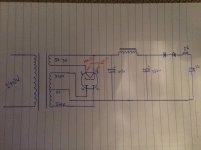
So I've redrawn it with the two resistors in series am in the right path now. Will the resistor values work for this design,is all for the reduction of hum ? Or not needed at all ? Or is there another way? Ps Thanks for the responses .
So I've redrawn it with the two resistors in series am in the right path now. Will the resistor values work for this design,is all for the reduction of hum ? Or not needed at all ? Or is there another way? Ps Thanks for the responses .
Attachments
5U4-GB filament (from Genereal Electric datasheet): 5V, 3A.
Don't use 0.27R dropping resistors, else your filament voltage will be only 3.38V!
" old tranny had winding centre taps but my new one doesn't"
Your last schematic contains CT trapped transformer. If you have this, this part of schematic is correct.
If you have transformer with 320V (no centre tap), use hibrid (two SS diode and rectifier tube) rectifier scheme.
Can we go back to the fundamental points?
1. Octal base rectifiers usually have a connection between the cathode and the heater (even when indirectly heated) so the heater supply must be independent and not connected to anything else - especially ground! In most cases a 5V supply is needed.
2. Other indirectly heated rectifiers may share a heater supply with the rest of the circuit - in most cases a 6.3V supply is needed. It does no harm to provide a heater supply centre tap, but the rectifiers don't need this. All heater supplies must have a DC reference voltage (which may be ground) which can be connected to one side or a centre-tap.
Sorry to confirm my 5v 3a filament winding had the centre tap
5U4-GB filament (from Genereal Electric datasheet): 5V, 3A.
Don't use 0.27R dropping resistors, else your filament voltage will be only 3.38V!
" old tranny had winding centre taps but my new one doesn't"
Your last schematic contains CT trapped transformer. If you have this, this part of schematic is correct.
If you have transformer with 320V (no centre tap), use hibrid (two SS diode and rectifier tube) rectifier scheme.
Thanks I think you've answered my question
I've put an artificial centre tap on all my other tubes but just wire the 5v winding straight to the rectifier tube no need to do anything else
Can we go back to the fundamental points?
1. Octal base rectifiers usually have a connection between the cathode and the heater (even when indirectly heated) so the heater supply must be independent and not connected to anything else - especially ground! In most cases a 5V supply is needed.
2. Other indirectly heated rectifiers may share a heater supply with the rest of the circuit - in most cases a 6.3V supply is needed. It does no harm to provide a heater supply centre tap, but the rectifiers don't need this. All heater supplies must have a DC reference voltage (which may be ground) which can be connected to one side or a centre-tap.
I've put an artificial centre tap on all my other tubes but just wire the 5v winding straight to the rectifier tube no need to do anything else
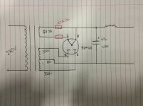
There's a hum that wasn't there before
New tranny is all installed tubes all in but there's a hum loud enough to notice.
I didn't have it with the old tranny above it said all heaters need a DC reference point can this be done in my schematic or anything else to suppress this new hum I have Whitch I'm sure is because I now have no centre tap on my filament winding any help would be fantastic I'm sooooo keen to listen to some tube again
Can we go back to the fundamental points?
1. Octal base rectifiers usually have a connection between the cathode and the heater (even when indirectly heated) so the heater supply must be independent and not connected to anything else - especially ground! In most cases a 5V supply is needed.
2. Other indirectly heated rectifiers may share a heater supply with the rest of the circuit - in most cases a 6.3V supply is needed. It does no harm to provide a heater supply centre tap, but the rectifiers don't need this. All heater supplies must have a DC reference voltage (which may be ground) which can be connected to one side or a centre-tap.
New tranny is all installed tubes all in but there's a hum loud enough to notice.
I didn't have it with the old tranny above it said all heaters need a DC reference point can this be done in my schematic or anything else to suppress this new hum I have Whitch I'm sure is because I now have no centre tap on my filament winding any help would be fantastic I'm sooooo keen to listen to some tube again
Attachments
Last edited:
The heater is internally connected to the cathode on pin 8, which is a DC reference point.
There is no way (nor need) to connect it to an other DC point.
The hum you are experiencing now is caused by something else.
Perhaps the voltages are slightly different and need some adjusting, or the new tranny radiates a stronger field.
Maybe it's best to open a dedicated thread on this?
There is no way (nor need) to connect it to an other DC point.
The hum you are experiencing now is caused by something else.
Perhaps the voltages are slightly different and need some adjusting, or the new tranny radiates a stronger field.
Maybe it's best to open a dedicated thread on this?
Last edited:
 Thread split off from filament wiring sticky
As almost any rectifier tube, due to prevent excessive surge current, requires a minimum resistance in its plate current circuitry, and as the total (and transformed) resistance of a power tranny's windings isn't sufficient in any case, I'd indeed provide an artificial center tap for a directly heated tube, consisting of two resistors of about 50 to 100 ohms.
An indirectly heated tube, e.g. the 5AR4, doesn't need this symmetrification. Simply connect the first filter cap to pin #8, the common pin for one heater end and the cathodes.
Good luck") !
!
An indirectly heated tube, e.g. the 5AR4, doesn't need this symmetrification. Simply connect the first filter cap to pin #8, the common pin for one heater end and the cathodes.
Good luck
!dear all,
I'd like to note an article about balancing the heaters of a directly heated rectifier:
http://www.tentlabs.com/InfoSupport/page35/files/Reducing_mains_ripple.pdf
best
Guido
I'd like to note an article about balancing the heaters of a directly heated rectifier:
http://www.tentlabs.com/InfoSupport/page35/files/Reducing_mains_ripple.pdf
best
Guido
- Status
- This old topic is closed. If you want to reopen this topic, contact a moderator using the "Report Post" button.
- Home
- Amplifiers
- Power Supplies
- When to use artificial center tap