I received a Private Message containing this request for a diode suggestion
Would anyone here like to recommend a diode part number for this scenario?I don't have any experience with this sort of application. Can you give me a suggestion for a suitable diode?
[I want to build a power supply circuit having] an 18V single winding (no CT), FW bridge, feeding 44,000uF, 0.22Ω, 44,000uF, giving 24VDC output. The load is 1.5A min. to 2A max. I am trying to avoid a soft start circuit if possible.
There will be 4 of these circuits in a 25W class A mosfet amp. Thanks very much.
My 2 cents worth.
44,000 uF
.22 ohm
2 A max load
18 vac in to a bridge rectifier
18 vac x 1.414 = 25.5 vdc
I = E / R
25.5 vdc / .22 ohm = 116 A min surge current for the second capacitor. The first capacitor has a lower resistance and a higher current. But the little 18 vac transformer can not supply this current. So as a rule of thumb start with double the maximum current rating of the circuit and see were you are. In your case 2 A max x 2 = 4A
A bridge rectifier of at least 50 V or 100 V for lots of safety.
Below is a selection of bridge rectifiers from DigiKey, starting from lowest price.
200 A surge current is my idea of minimum, a large OEM would probably use this one to save money. 250A is plenty of safety. 300 A surge is overkill. I would go with the KBU6B for specs and price, 250 A surge and 100 V.
If you wanted to limit the surge current then you would use a
inrush Current Limiters (ICL)
These devices are inexpensive and work well.
Bridge rectifiers.
KBL005-E4/51
4A, 50 V, 200 A surge current.
$1.32
KBL01-E4/51
4A, 100 V, 200 A surge current.
$1.32
RS401GL-BP
4A, 50 V, 200 A surge current.
$1.33
RS402GL-BP
4A, 100 V, 200 A surge current.
$1.33
KBU6B
6A, 100 V, 250 A surge current.
$1.45
GBU8B
8A, 100 V, 200 A surge current.
$1.66
KBU8A
8A, 50 V, 300 A surge current.
$1.56
BR81
8A, 100 V, 250 A surge current.
$1.85
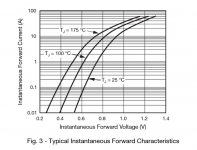
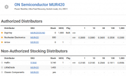
If you're considering using discrete diodes instead of bridge rectifier assemblies, the MUR420 (datasheet) might be worth putting on your shortlist. It's an ultrafast diode with pretty nice soft recovery characteristics BUT unlike many other soft recovery parts, it does not have an enormous Vfwd; its Vfwd as low or lower than a standard silicon diode in a standard bridge. See image below. So you don't pay a penalty in excess voltage drop or excess heat.
It's an axial lead package, rated 4 amps and 200 volts. Max instantaneous forward current is 150 amperes, which is undoubtedly more than the secondary can possibly deliver. You know, Imax = Vsecondary / Rcopper and all that.
Best of all, the MUR420 is pretty cheap: USD 0.28 in quantity one; see image below.
_
Attachments
http://www.mouser.com/ds/2/149/GBU6D-195619.pdf 50 cents in quantities
everybody makes this package ( GBU-4 ) seen on ATX supplies and others
no soft start needed for less than 300VA
>400VA start thinking about soft start for wear n tear for the On-Off switches.
use slow diodes for mains frequency rectifiers ! high speed diodes are made for SMPS
then usually call for duals not singles.
Last edited:
I use 25A or 35A bridge rectifiers for most of my PSUs and these are generally either 40mF or 45mF capacitance.
I have never blown the rectifiers.
I have used higher capacitance in a few builds, upto +-75mF using the same bridge rectifiers.
But all my transformers use a soft start.
I have never added a slow charge circuit to limit the capacitor charging current.
BTW,
a transformer can survive massive overload for short periods.
The short circuit secondary current is limited by the effective impedance of the secondary and can easily exceed 100Apk for a 300VA 230:35+35Vac transformer.
note this is for a 50W PA circuit with poor PSRR. probably not what you typically use.I use 25A or 35A bridge rectifiers for most of my PSUs and these are generally either 40mF or 45mF capacitance.
I have never blown the rectifiers.
the XFMR maybe rated around 150-200VA or so, or using two for 4 windings.
Last edited:
are you sure?note this is for a 50W PA circuit with poor PSRR...................
a 25W class A mosfet amp
One easy way to (over)estimate the max possible diode current is to assume the diode and capacitors are a DEAD SHORT, and assume the transformer is ideal in every way except its secondary has nonzero resistance. Then max secondary current is determined solely by secondary resistance. You can measure this resistance with your multimeter.
The transformer in the Original Post has a 115VAC primary and four 18VAC secondaries, each secondary rated ~ 3.5 amperes RMS (63 VA per secondary; 250 VA for the transformer). I just measured the secondary of a comparable toroidal transformer using my Keithley 177, and found that Rsecondary was 0.3 ohms. I am confident that when the OP measures his transformer he will get a similar value.
The max possible current, by Ohm's Law, is thus Vsecondary/Rsecondary. Numerically, Imax = 18 / 0.3 = 60 amperes.
As mentioned in the first sentence, 60 amps is an overestimate, because it neglects all other loss mechanisms. It ignores the resistance of the primary (which reflects into the secondary by the reciprocal of the turns ratio squared), it ignores hysteresis losses in the core, it ignores below-100% flux linkage from primary to core and from core to secondary, it ignores eddy current losses, and so forth.
I'm sure the thought has occurred to readers, that even if they don't have the actual transformer on the bench to measure, they can still calculate a workable estimate merely from the secondary's voltage and current rating. One simply assumes a value for secondary "regulation", i.e., voltage drop under load. Then Ohm's Law calculates an equivalent resistance for this assumption, which we (arbitrarily!) assign half to the primary and half to the secondary. Example: Let's assume the OP's transformer has 10% regulation, i.e., 10% lower voltage at full load than at no load. Then R = (Vnoload - Vfulload)/Irated = (20V - 18V)/3.5A = 0.57 ohms equivalent resistance. Half of this is secondary resistance, and half is primary resistance (reflected back through the square of the turns ratio). So Rsecondary = 0.285 ohms. Reasonably close to the 0.3 ohms measured on a comparable transformer's secondary.
Last edited:
Mark, that was a very impressive post. I used your method to compare to Andrews post and i think they are in the ball park.
"The short circuit secondary current is limited by the effective impedance of the secondary and can easily exceed 100Apk for a 300VA 230:35+35Vac transformer. Andrew T"
300va / 35vac = 8.57A
35vac x 10% = 38.5vac
38.5vac - 35vac = 3.5vac
3.5vac / 8.57A = .408 ohms
.408 ohms / 2 = .204 ohms secondary
35vac / .204 ohms = 171A surge
Class A with Pout = 25W max, needs 50W min.are you sure?
so based on no other information, sure
I use MBR1045 (10A/45V) up to 1.5 load, and MBR1635 (16A/35V) up to 2.5A.I received a Private Message containing this request for a diode suggestion
Transformer secondary must be minimum 5A capable (at 2.5A load), diode peek current about 11A (graetz- 0.1R - 2*10mF -0.1R DCR 5mH - 10mF - 0.33R DCR CMC - 2*10mF).
Hum only 8mVpp.
I use Panasonic TSHA capacitors.
Class A
Total power consumption would be 50 watts with 25 watts into the load.
Alas that Pi circuit has an instantaneous impedance of 25 milli ohms at the FW bridge
that's like 1000 amp surge at 25 peak volts
The core of the transformer will saturate way before that can happen. With the core saturated the secondary turns off and the core becomes magnetized briefly. Until the next cycle comes along and reverses the core saturation. The core will continue to saturate until the charge current drops below, what it takes to saturate the core.
Now that's soft start.
are you sure?
Total power consumption would be 50 watts with 25 watts into the load.
Alas that Pi circuit has an instantaneous impedance of 25 milli ohms at the FW bridge
that's like 1000 amp surge at 25 peak volts
The core of the transformer will saturate way before that can happen. With the core saturated the secondary turns off and the core becomes magnetized briefly. Until the next cycle comes along and reverses the core saturation. The core will continue to saturate until the charge current drops below, what it takes to saturate the core.
Now that's soft start.
Raypsi, I know this is going to sound crazy to you but you cannot saturate a transformer core with a load on the secondary. The only thing that can saturate a core is too much primary voltage. As the primary voltage increases the magnetic field around the core must increase. When the core can no longer support the magnetic field called for, it is saturated, and at that point the transformer is no longer an inductor, it is a piece of wire acting as a short circuit.
The only good news about this is that iron transformers have a very shallow saturation point. The current keeps climbing and climbing as you increase the primary voltage until the wire is to hot and burns up.
Ferrite transformers are different as they have a fairly sharp cut off. A few hundred Gauss over the limit and your transformer is saturated.
- Status
- This old topic is closed. If you want to reopen this topic, contact a moderator using the "Report Post" button.
- Home
- Amplifiers
- Power Supplies
- Diode help! 18VAC --> diodes --> CRC 44mF-0.22R-44mF --> 24VDC @ 1.5-2.0A