
hi everyone
my areas electricity makes high frequency noise in any audio amplifier.
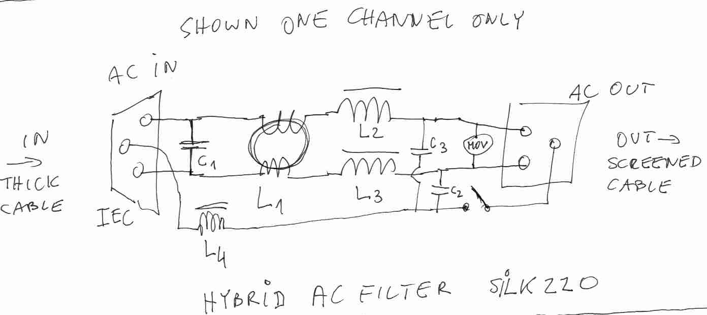
I wanet to get rid of that so I searched and ended up with this mains filter
but my my apartemant has not earth. so any suggestion?
You don't need the earth connection, if there is no third wire. Leave off the two capacitors.
You can also try adding a 10 uF 800V capacitor across the incoming line. A 240 volt line is 680 volts peak to peak! It can go as much as 10% higher.
Be sure all the parts are rated for across the line use.
You might also want to fuse things.
another thing Is the RC filter before the transformer in this circuit for mains filtering?
or its for current surge in transformer?
If current surge, can I use it for any trans or for lower VA transes? or the value of capasitor in RC filter should be decreased?
or its for current surge in transformer?
If current surge, can I use it for any trans or for lower VA transes? or the value of capasitor in RC filter should be decreased?
Attachments

Last edited:
You don't need the earth connection, if there is no third wire. Leave off the two capacitors.
You can also try adding a 10 uF 800V capacitor across the incoming line. A 240 volt line is 680 volts peak to peak! It can go as much as 10% higher.
Be sure all the parts are rated for across the line use.
You might also want to fuse things.
tnx for reply
what would be the cut-off freq of low pass filter for 10uF cap?
On a 240V line you will never get 680V or smg is seriously wrong, although X2 and Y2 caps are also at leask 1kV certified for a reason.
Caps on the front are used not to filter the incoming, but the outgoing frequencies that your device generates. Like at PC PSU. LC filter is LC and not CL, because L comes first and than C.
Plus many times they put the VDR (or MOV) also to the front so they catch the incoming spike before it may even damage the filter caps.
There are a lot of online low pass filter calculators.
9Ohm and 220nF gives 80Hz. Seems a bit low to me unless the system doesn't require much power.
Last edited:
A 230/240 Volt supply is derived from a three phase HV supply transformed via a number of transformers from 550kV ( pylon voltage, high voltage means low current) to 33kV (Industrial estate and Town supply) to 415V (Commercial supply for machines). The 415V supply is between phases and in a star configuration, 230/240V phase to centre star or Earth. The maximum voltage peak to peak of a 230/240V supply is therefore nominally 415V.
I guess people are a bit hazy from the weekend 😀
230V is the RMS value. It's peak is sqrt(2) times that, or 325V.
Peak to peak is therefore 650V. However as the mains is a floating source (we are not talking about ground referenced source like loudspeaker), 325V is as big a magnitude it's ever going to get, i.e. it is already in effect peak to peak. Only in the case of a capacitor or something remaining charged will a peak to peak voltage ever been seen.
Last edited:
A medical version of the Mains Filter omits the Y1 or Y2 capacitors and uses just the X1 or X2 capacitors, the inductors and the charge depleting resistor. It does not require the PE connection.
The peak voltage of the sinewave is sqrt(2) times the Vac.A 230/240 Volt supply is derived from a three phase HV supply transformed via a number of transformers from 550kV ( pylon voltage, high voltage means low current) to 33kV (Industrial estate and Town supply) to 415V (Commercial supply for machines). The 415V supply is between phases and in a star configuration, 230/240V phase to centre star or Earth. The maximum voltage peak to peak of a 230/240V supply is therefore nominally 415V.
For nominal 240Vac here in the UK we get 339.4Vpk, 253Vac becomes 357.8Vpk
But all our mains is contaminated with spikes and glitches.
The spikes can exceed 1kVpk
The filter components must be rated to be safe in the presence of these spikes. Y1 are rated to around 8kV
X1, X2, Y1, & Y2 Classifications
Class X and Y capacitors are also given a number to represent their impulse test rating. The most common are X1 (tested to 4,000 volts), X2 (2,500 volts), Y1 (8,000 volts) and Y2 (5,000 volts).
tnx all for reply,
went to electronic shop and unfortunately didnt find x1 grade caps
so searched over Internet and found mkt capacitors [100nF 275V & 1nF 400V]
but dont know if they are x1 grade or not. are all mkt caps x1 or x2 grade?
and for 1nF 1KV there was just poly. caps
for indutor found single toroid 1.8 mH. should buy four
and for Varistor found VDR10K361. detail on site says 10mm 230Vrms 300Vdc 2500.
Is this right? seems wrong. shouldnt be 361vdc?
should I choose diferent VDR?
In this condition and lack of components Is it wise to make this circuit? Its mains after all
just want to get rid of the damn noise
Last edited:
Plus many times they put the VDR (or MOV) also to the front so they catch the .
should I do this too? is it better to move vdr to main input? or even add one there?
A 250Vac VDR or MOV is probably rated too low for use on 230Vac Mains supplies where the maximum voltage can approach 253Vac.
we use 275Vac rated VDR or MOV for our 240Vac supplies.
230Vac is definitely too low for 220/230Vac supplies.
X1 and Y1 are generally used on 400Vac supplies (3phase)
X2 and Y2 are used on 230Vac supplies (single phase).
Only use X & Y rated capacitors across the Live Mains.
we use 275Vac rated VDR or MOV for our 240Vac supplies.
230Vac is definitely too low for 220/230Vac supplies.
X1 and Y1 are generally used on 400Vac supplies (3phase)
X2 and Y2 are used on 230Vac supplies (single phase).
Only use X & Y rated capacitors across the Live Mains.
If you do a search for "Shunyata DIY", you will find some details that may help you construct a filter.
I made mine inside a grounded, metal case power strip, connections crimped for thermal safety. I also used a pair of chokes that I symetrically wound with each leg as well as the X capacitors. It made a great difference for me, but I am in a factory...
It can be hard sometimes to get diy advice for matters that deal with high currents, as most of us don't want to be responsible for someone else getting into trouble, or getting hurt; this can be potentially dangerous stuff so be safe.
tnx all for reply,
went to electronic shop and unfortunately didnt find x1 grade caps
so searched over Internet and found mkt capacitors [100nF 275V & 1nF 400V]
but dont know if they are x1 grade or not. are all mkt caps x1 or x2 grade?
and for 1nF 1KV there was just poly. caps
for indutor found single toroid 1.8 mH. should buy four
and for Varistor found VDR10K361. detail on site says 10mm 230Vrms 300Vdc 2500.
Is this right? seems wrong. shouldnt be 361vdc?
should I choose diferent VDR?
In this condition and lack of components Is it wise to make this circuit? Its mains after all
just want to get rid of the damn noise
No the chokes are actually transformers that take the interference from one leg and invert it to be in series with the other leg. As they are of construction they work for high frequencies and not the mains frequency.
Go Balanced
Audible noise and hash can be the devil to get rid of. The problem with the great majority of power supply based common-mode filter designs is that while they are effective on ultrasonic and RF noise, they typically aren't sized to be effective enough on audible noise. I've implemented both commercial and DIY powerline filters with little subjective reduction in audible noise and hash. Even if you obtain a power conditioner that's sufficiently effective at audible frequencies, and plug all of your components in to it, you still could possibly have common-mode noise currents circulating between components across the signal interfaces. Assuming that your noise problem is intercomponent common-mode in origin, the most effective cure would be to implement true balanced signal interfaces between your components. This solution, while the best performing at audible frequencies, could get costly if quality signal transformers are required. This is what professional studios do.
By the way, if the power mains wiring to your home lacks a safety ground, hopefully your local electrical code allows you to replace the wall mounted power receptacles with 240V rated GFCI (Ground Fault Circuit Interrupter) receptacles of the proper amperage. GFCI receptacles are inexpensive and could save your life or the life of a loved one. I strongly recommned looking in to this, especially should you actually have 240V power mains as is indicated in your filter schematic.
Last edited:
Hi from Spain,
I have a very long spanish thread you must read:
-> USB Isolator: iFi iUSB vs TeraDak U9VA + Teralink ADuM4160. Filtros Schaffner. Lampizator: AC filter DIY ESA SILK. Estabilizador / regulador de tensión / voltaje. Isolation / Balanced transformer. DC Blocker / Blocking. PC SILENCIOSO en Aussar. Vari
To english with GT:
-> https://translate.google.es/transla...ilencioso-en-aussar-variac&edit-text=&act=url
I have too much RFI/EMI, DC and riple in mains. With Schaffner filters, RFI Würth ferrites and DC blocker I have mitigated much the problem.
You can read too, from Lampizator:
-> AC filterr DIY ESA SILK
-> -> AC filter by Lukasz F.


- Status
- Not open for further replies.
- Home
- Amplifiers
- Power Supplies
- Mains Filter