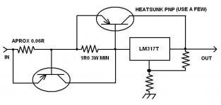
Linear regulator with current boost and current limiting.
Buck/Boost using transformer as voltage adjustment device...pick your transformer(s) for voltage adjustment...much cheaper than auto-transformer or Variac.
Buck/Boost using transformer as voltage adjustment device...pick your transformer(s) for voltage adjustment...much cheaper than auto-transformer or Variac.
Attachments
Buck/Boost using transformer as voltage adjustment device...
That is a SMPS. These have been categorically rejected by virtually every thread in this forum and elsewhere. The idea is great, but there is RFI emission, and subsequent filtering is also required. In addition, they have a much shorter lifespan than traditional regulators and are considered disposable devices.
That is a SMPS...
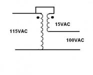
Not a SMPS at all...It is a transformer, plain and simple. Phased as required it can increase (Boost) or decrease (Buck) the load side voltage. The secondary current rating should be equal to or greater than the load current.
...SMPS. These have been categorically rejected by virtually every thread in this forum and elsewhere...
I disagree.
...but there is RFI emission...
Technically there is RF emission in a 50/60Hz transformer/diode/filter supply, but the frequency and propagation is lower so you don't notice it. So I guess the RF emission comes down to design.
...In addition, they have a much shorter lifespan than traditional regulators and are considered disposable devices.
I disagree about the lifespan. I would think that comes down to design for both types. The disposable part I would partially agree that they are produced so cheaply that it is more economical to replace than repair. I would not consider these: Audio Power - Audio Smps as disposable.
")
Last edited:
Not a SMPS at all...It is a transformer, plain and simple. Phased as required it can increase (Boost) or decrease (Buck) the load side voltage. The secondary current rating should be equal to or greater than the load current.
I fail to see how a linear regulator can change the output voltage of a transformer.
I did not know that someone finally made audio-grade SMPSs. The shield around the ferrite transformer is noteworthy. They appear to be built to last. Only problem is if they fail, they are dead. With the tap-switching autotransformer, if the circuit fails, one of the tap relays will most likely be closed to provide power. Thank you for exposing the company.
I have not checked the prices of those, but two of the tap-switchers
will cost under $150 plus the shielding--about $30. And you have a spare controller.
I would guess any of those options would be feasible for regular audio, but not a high gain guitar amp. If you look at the traditional layout--see Soldano SLO-100--plenty of clone pics on internet. Turn the power transformer 90 deg. and the amp will buzz, and it's mounted outside and above a steel chassis.
My new amp design has the heaters and HT regulated with plenty of headroom for say 100/200VAC going in. The heater voltage or the HT voltage alone being low is not much of a problem but not both at the same time.
I have picked up transistor switching noise in my old design which measured high magnitude around 600kHz. That was from a 555 timer and sink transistor used for circuit switching. That all had to go outside the chassis. The poor design with long wires may have been the problem, though.
The point is that if you get injection, prepare to spend perhaps months trying to get it quiet.
I still don't know if low mains will have any appreciable effect on my new design in the first place. I still have to check. I will play it safe and go with the isolated volume adjustment for my high-gain application.
Last edited:
I fail to see how a linear regulator can change the output voltage of a transformer...
You are correct, it cannot.
My #41 post was two solutions to two different ways to compensate for variations in AC supply potential. One for a static variation (fix at AC level) and one for dynamic variations.(fix at DC levels)
...I have picked up transistor switching noise in my old design which measured high magnitude around 600kHz. That was from a 555 timer and sink transistor used for circuit switching. That all had to go outside the chassis. The poor design with long wires may have been the problem, though...
I tend to ignore noise (~600KHz) that I cannot hear. I use small pcb mounted DC-DC switchers (~100KHz) for my home stereo pre-amp. Between the small R-C filter at each op-amp supply pin and the PSRR of the op-amp I have more than 120dB rejection (calculated) of any supply ripple. No noise at speaker.
I would like to tap your knowledge of guitar amp builds with a question because a guitar amp is on my list of projects. (big list)
What is your input sensitivity for full power output (linear)?
Thanks
I tend to ignore noise (~600KHz) that I cannot hear....
What is your input sensitivity for full power output (linear)?
Thanks
My amp was somehow demodulating (if that's the correct term) at that frequency which resulting in a fairly loud single "pop". The transistor(s) in the control circuit produced this frequency when it transferred. So there was 0 frequency of the event, but the sharp edge of the square produced the noise. http://www.hottconsultants.com/pdf_files/APEC-2002.pdf
The long wires connected to high gain areas were acting as antennas.
I rounded the edges by adding capacitors and mounting half the control circuit on the pedal board.
So the switching frequency is not an issue except perhaps if it falls within the audio range. It is the transistors themselves that is the problem. One could also use huge value resistors in the gate circuit, but that would decrease efficiency by some extent.
The input sensitivity is adjustable. The amp can actually output over 120W. For 100W into 4 ohms, perhaps around 200mV. But where the distortion is created the gain goes in stages, attenuated about 1/2 after each stage of 60, 60, 40, then the last stage another 60 which is reduced to line level for the solid state power amp.
The first input device is RFI's favorite victim, as well as magnetic induction from the transformers.

- Status
- This old topic is closed. If you want to reopen this topic, contact a moderator using the "Report Post" button.
- Home
- Amplifiers
- Power Supplies
- LM317 + 2 Transistors "Class A" Regulator?