Good. Please note that these make cabling of devices a little safer.
I know, indeed a little......
Nice!
Thank you J-P. The SBT PSU is a very good power supply.
I was always curious if I could hear a difference with my SBT because I am running digital out with an external DAC. I had expected that any sound improvements would more likely affect the analog circuits, but the improvement is clear. The thing that I notice the most is a blacker background. It was noticeable immediately.
I also experimented with and without the snubber. With the snubber is a small difference, but I think worthwhile. I feel like I can hear a bit more detail with the snubber.
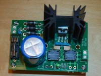
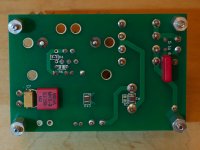
On the topic of the snubber, if additional boards were ever made, it is the one place where an improvement in component placement would be helpful. Of course, I was trying to use components that I already had. The room allowed for C1 was too small for any of the caps that I had available. On the suggestion of another builder, I swapped R1 and C1 and put C1 on the bottom of the board. Since I needed a 1/2 watt resistor for R1, I mounted it soldier style and it worked fine. That said, the lower hole for C1 was half covered by the fuse holder, so a more room would be useful. There is no way to put a component on top of the board in the lower position.
I noticed that Loek had added an additional capacitor at the output on the bottom side of the board. I thought that was a good idea, but I added a small value film cap instead of a 'lytic' with the idea of keeping the impedance low at higher frequencies.
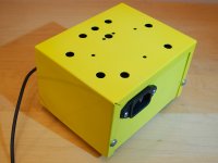
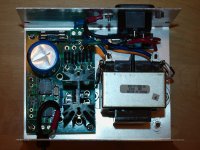
The enclosure is a reuse of a box from one of my father's old projects. It needed paint to cover the markings from the old project. Since it wouldn't be visible most of the time (sitting behind and below the primary audio components), I thought, "Let's have some fun." Hence, the yellow color.
The holes in the top are left over from my father's project and, combined with holes on the bottom, the regulator stays less than 10 degrees above ambient when driving the SBT.
Jac
Thank you J-P. The SBT PSU is a very good power supply.
I was always curious if I could hear a difference with my SBT because I am running digital out with an external DAC. I had expected that any sound improvements would more likely affect the analog circuits, but the improvement is clear. The thing that I notice the most is a blacker background. It was noticeable immediately.
I also experimented with and without the snubber. With the snubber is a small difference, but I think worthwhile. I feel like I can hear a bit more detail with the snubber.
On the topic of the snubber, if additional boards were ever made, it is the one place where an improvement in component placement would be helpful. Of course, I was trying to use components that I already had. The room allowed for C1 was too small for any of the caps that I had available. On the suggestion of another builder, I swapped R1 and C1 and put C1 on the bottom of the board. Since I needed a 1/2 watt resistor for R1, I mounted it soldier style and it worked fine. That said, the lower hole for C1 was half covered by the fuse holder, so a more room would be useful. There is no way to put a component on top of the board in the lower position.
I noticed that Loek had added an additional capacitor at the output on the bottom side of the board. I thought that was a good idea, but I added a small value film cap instead of a 'lytic' with the idea of keeping the impedance low at higher frequencies.
The enclosure is a reuse of a box from one of my father's old projects. It needed paint to cover the markings from the old project. Since it wouldn't be visible most of the time (sitting behind and below the primary audio components), I thought, "Let's have some fun." Hence, the yellow color.
The holes in the top are left over from my father's project and, combined with holes on the bottom, the regulator stays less than 10 degrees above ambient when driving the SBT.
Jac
Attachments
Nice build! Lehmanhill.
The reason for my extra cap is that i only had 2 of 47uF caps instead of 3. So the last one is a smd 10uF plus an extra 33uF radial cap.
Thanks.
Like your extra cap, I used a lot of parts from my parts drawer too. Anyway, there is space for an extra cap there, so it was a good idea and I thank you for it.
Jac
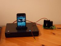
I've finally completed my PSU. I was a bit nervous about the tiny surface mount stuff but with a fine tip and solder it was easier than I thought (with a magnifying glass on a small stand). I built the standard version which measures as 4.96 volts. My plan is to use it with a RPi and an I2S DAC but as that isn't ready yet, to try it out, I wired it up to power a ONKYO ND-S1 (an IPOD dock which extracts the digital signal from the multi-pin connector). I'm hopeless at assessing audio differences but it sounds very good to my ears and I prefer it to the original (switched) PSU.
Many thanks to J-P.
Many thanks to J-P.
Attachments
No PCBs anymore but I have a few ready built PSU's so PCBs that are stuffed and tested.
*News for Canadian/USA builders: I have found an affordable way to send Rcore transformers to you. Shipping is 10 Euro for 1 piece but also 2 depending on how I pack them. Best would be to make it a group order and send many of them in a box. So if any of you guys want one please send me a PM. Transformer price is 17,50 Euro/piece.
Being European is not a sin (no it is definitely a joy like many sins") ) so also European guys can have one or more.
) so also European guys can have one or more.
*News for Canadian/USA builders: I have found an affordable way to send Rcore transformers to you. Shipping is 10 Euro for 1 piece but also 2 depending on how I pack them. Best would be to make it a group order and send many of them in a box. So if any of you guys want one please send me a PM. Transformer price is 17,50 Euro/piece.
Being European is not a sin (no it is definitely a joy like many sins
) so also European guys can have one or more.
Last edited:
Last post in this thread as far as I am concerned.
Recently quite a few PSUs of my stock have been sent out but I have the last 2 stuffed boards and still 10 Rcores left.....
The Rcores can also be used to replace less good transformers in DACs etc. These are absolutely silent, have a very low stray field and they are 6V 3A. Ideal for 5V PSUs.
Recently quite a few PSUs of my stock have been sent out but I have the last 2 stuffed boards and still 10 Rcores left.....
The Rcores can also be used to replace less good transformers in DACs etc. These are absolutely silent, have a very low stray field and they are 6V 3A. Ideal for 5V PSUs.
That wasn't the last post . Got an email from a Diyaudio member which says that the right snubber values are a 0.1uf capacitor in series with ~150-170 ohms.
I would make that a 150 Ohm 1W resistor and a 0.1 µF film capacitor rated for at least 50V DC/30V AC like Wima MKS 4. Haven't tried myself yet so I only can pass this information. Will try it out when I have the time.
. Got an email from a Diyaudio member which says that the right snubber values are a 0.1uf capacitor in series with ~150-170 ohms.I would make that a 150 Ohm 1W resistor and a 0.1 µF film capacitor rated for at least 50V DC/30V AC like Wima MKS 4. Haven't tried myself yet so I only can pass this information. Will try it out when I have the time.
I probably have the snubber parts floating around though I suppose I could build it then add them later. One question- my line voltage is generally closer to 124 than 115, 8% extra dissipation is probably not an issue? Or would I be better served to put a diode or two on the trafo secondary to board connection?
Putting it in an old scrap case and will ventilate bottom and top.
Putting it in an old scrap case and will ventilate bottom and top.
overkill
1W is overkill for the snubber resistor. The 0.1uf capacitor blocks the 50/60hz since it creates a high pass filter with -3db point of ~ 10khz. The dissipation of the resistor due to the transformer AC voltage is a fraction of a milliwatt. So 1/4 watt or 1/8 watt resistors are just fine for the snubber.
---Gary
That wasn't the last post
I would make that a 150 Ohm 1W resistor . . .
1W is overkill for the snubber resistor. The 0.1uf capacitor blocks the 50/60hz since it creates a high pass filter with -3db point of ~ 10khz. The dissipation of the resistor due to the transformer AC voltage is a fraction of a milliwatt. So 1/4 watt or 1/8 watt resistors are just fine for the snubber.
---Gary
badman,
Just my opinion, but I wouldn't worry about it. My voltage is like yours and my SBT PSU has been running cool and at voltage for months.
Jac
Great, I figured it was probably okay but really nice to have a user verify
I think I have some .1 silver micas that would work nicely for snubber duty, I suppose I'll just toss that stuff aboard before I finish the casework, re-using an old project case, a little big but that's not such a biggie.
My recently assembled SBT PSU will be powering a BeagleBone Black. I was not intending to earth the DC -ve output of the SBT PSU ...
but now I see that there is electrical continuity between the BBB's -ve DC input connection and the sleeves of its 4 PCB mounting holes. Clearly, then, this device was designed to have its -ve supply earthed.
What do others think - should I use metal standoffs and earth the DC input to the BBB, or instead use nylon standoffs and keep the DC supply floating?
Thanks.
Why would you earth the DC- of the SBT psu? It can give you more trouble than without.My recently assembled SBT PSU will be powering a BeagleBone Black. I was not intending to earth the DC -ve output of the SBT PSU ...
but now I see that there is electrical continuity between the BBB's -ve DC input connection and the sleeves of its 4 PCB mounting holes. Clearly, then, this device was designed to have its -ve supply earthed.
What do others think - should I use metal standoffs and earth the DC input to the BBB, or instead use nylon standoffs and keep the DC supply floating?
Thanks.
- Status
- This old topic is closed. If you want to reopen this topic, contact a moderator using the "Report Post" button.
- Home
- Amplifiers
- Power Supplies
- Building the SBT PSU