Search some of the older tube regulator threads here, you'll find designs by Frank DeGrove, me and several others that should be of interest.
Also have a look for the 1955 - 1960 edition of the U.S. Navy Preferred Circuits manual. There are some very good VR designs in the manual.
http://www.virhistory.com/navy/manuals/NAVAER16-1-519-1.pdf
Also have a look for the 1955 - 1960 edition of the U.S. Navy Preferred Circuits manual. There are some very good VR designs in the manual.
http://www.virhistory.com/navy/manuals/NAVAER16-1-519-1.pdf
I'm looking for a tube based regulator schematic...
I have some tested circuits with 6AS7G and ECL85, but before I suggest anything, I would like to know:
- What current ?
- What is +Ub to regulator.
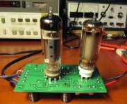
Attachments
Hi,
Salas regulator is a shunt regulator.
It's hard to beat so you'll really need to look at valve based shunt regs.
In my book shunt regs offer superior regulation at the expense of cost and wasted energy.
They're simple constant current devices.
Series regs add complication, waste less energy and depending how you design the error amp they can be very precise voltage wise.
What you need to consider either way is he output impedance of the regulator versus frequency across the af band you want.
Needless to say you want it low and fast.
Assuming a series reg, you want the pass valve to have as high perveance as possible.
Should you want high precision then you'd want to opt for a cascode error amp which yield very high error correction with hardly any noise added.
I use gas reference tubes as I do not like the sonic impact of zener diodes. Gas tubes can be very quiet and precise.
They just got a bad rep for most US gas tube reference are noisy and lack precision.
Anyways, most people don't have a clue on how to use them properly anyhow.
After that you'd want this low output Z across the audio band, the larger the better.
Since you already have a very well filtered DC supply by now, you should use wide band electrolytic caps of quite large value and low esr. Putting caps in // is one way to up capacitance and reduce esr at the same time.
If you can afford it and the reg's output is dead quiet, use filmcaps.
These can be of much lower value and the entire circuit will sound much faster and cleaner throughout.
Whenever I design something worthy of challenging the best I opt for dual mono designs and use separate regs for every stage that draws more current then the next etc.
At no time the current draw by one stage should be influenced by the next.
Then , and only then you can achieve true stereo imaging which is stable at all time.
Keep in mind that when you regulate one stage you really should regulate alle of them for best results.
Best regards and happy birthday to Kenny,
")
Salas regulator is a shunt regulator.
It's hard to beat so you'll really need to look at valve based shunt regs.
In my book shunt regs offer superior regulation at the expense of cost and wasted energy.
They're simple constant current devices.
Series regs add complication, waste less energy and depending how you design the error amp they can be very precise voltage wise.
What you need to consider either way is he output impedance of the regulator versus frequency across the af band you want.
Needless to say you want it low and fast.
Assuming a series reg, you want the pass valve to have as high perveance as possible.
Should you want high precision then you'd want to opt for a cascode error amp which yield very high error correction with hardly any noise added.
I use gas reference tubes as I do not like the sonic impact of zener diodes. Gas tubes can be very quiet and precise.
They just got a bad rep for most US gas tube reference are noisy and lack precision.
Anyways, most people don't have a clue on how to use them properly anyhow.
After that you'd want this low output Z across the audio band, the larger the better.
Since you already have a very well filtered DC supply by now, you should use wide band electrolytic caps of quite large value and low esr. Putting caps in // is one way to up capacitance and reduce esr at the same time.
If you can afford it and the reg's output is dead quiet, use filmcaps.
These can be of much lower value and the entire circuit will sound much faster and cleaner throughout.
Whenever I design something worthy of challenging the best I opt for dual mono designs and use separate regs for every stage that draws more current then the next etc.
At no time the current draw by one stage should be influenced by the next.
Then , and only then you can achieve true stereo imaging which is stable at all time.
Keep in mind that when you regulate one stage you really should regulate alle of them for best results.
Best regards and happy birthday to Kenny,
I have some tested circuits with 6AS7G and ECL85, but before I suggest anything, I would like to know:
- What current ?
- What is +Ub to regulator.
Small current are for phono pre and line pre: 26, mu-follower, Salas valve Itch.
What is +Ub to regulator. I'm sorry I don't understand your question.
Anyways, most people don't have a clue on how to use them properly anyhow.
Indeed. I should get off my *** and try a cascoded CCS feeding one those monster gas tubes - an STR 280/80 in my case. Certainly won't beat the low impedance of a good mosfet shunt, but may still provide an interesting sonic alternative.
And Frank's golden words remind me that most people don't have a clue how to use a depletion mosfet ccs either
The damn things require at least a 100v across to wake up and sing. Yes, Salas says ten volts are plenty enough, but here i beg to differ.
You use SSHV2 with a difference between Vin/Vout of 100V?
Salas not just says, Supertex shows. 10V are enough to bring the parasitic capacitances down, 20V that I advise for SSHV2 in its guide are bringing them all fully down. Nothing else changes electrically beyond that threshold other than adding dissipation.
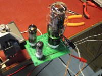
Attachments
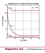
Salas not just says, Supertex shows. 10V are enough to bring the parasitic capacitances down, 20V that I advise for SSHV2 in its guide are bringing them all fully down. Nothing else changes electrically beyond that threshold other than adding dissipation.
That ignores the magic and mystery.
What is +Ub to regulator. I'm sorry I don't understand your question.
+Ub means the rectified supply voltage in this case.
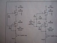
For currents up to 50 mA the ECL85 (or soviet 6F5P) is sufficient.
The schematic is attached. By scaling R6 and P1 the required voltage adjustment range is got. With the component values shown, the output voltage can be adjusted from 180 V to 280 V.
I would recommend to adjust the input voltage of the pass tube about 100 V higher than output voltage. This can be done with R7 /R8.
Attachments
With regard to cascoded MOSFET CCSs, most of the voltage is across the upper devise. In most circuits that I am aware of the voltage across the bottom devise is limited to the Vgs of the upper MOSFET which is less than 4V. Walt Young proposed a modification to the cascode CCS in the letters section of the April AudioXpress. With the addition of two resistors and a Capacitor the voltage across the lower devise can be increased by 4X.
Attachments
- Status
- This old topic is closed. If you want to reopen this topic, contact a moderator using the "Report Post" button.
- Home
- Amplifiers
- Power Supplies
- tube regulator for B+