Hello guys.
I'm about to make my very first ever smps.
I have enough of practical knowledge, and quite a bit of theory, but all that is a self taught, so in order to make my smps happen, I need alot of help from outside world")
The majority of help I need is to do with a calculating transformer core size, and all the associated key parameters.
The basic plan is:
8 - 30VDC
0 - 1000A
10kW
OCP, OVP, OPP, OTP,
10 turn pot for voltage
10 turn pot for current
Full bridge topology, initially based on two of SKM100GB128 or LUH75G1201 or something similar
Main transformer based on Amorphous / Nanocrystaline core, roughly 120/70/20 mm size toroid with just under 4cmsq of cross section (calculations needed)
Switching frequency around 20kHz
Multiple, center tapped secondary, and multiple output rectifier diode modules, something like MBRP400200, and individual output inductor per every center tap
Output filtration in LCLC fashion if needed to limit output voltage noise
Secondaries wound for a 5A/sqmm current density
Fully isolated control and driver circuit from power electronics (AC/DC/Pulse current transducers to keep pulse-by-pulse current control fashion, and TL431 with transoptor for voltage control)
Supply voltage 570VDC initially (rectified 415VAC 3Ph), and 800VDC in it's final stage when Active PFC will come to life (transformers primary will need to be rewired for that case I guess ?)
Initially hard switching with UC3846, but may need to go for soft switched, also based on UC3846
Due to my work, I have quite good resource of power electronics and such.
The real help I need is the amorphous / nanocrystaline cores info, and a general explanation of LLC soft switched SMPS's
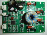
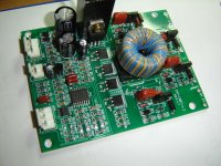
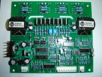
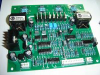
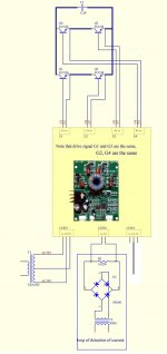
Attached are pics of two driver boards. The smaller one is a UC3846 based, fully isolated hard switching driver, the bigger one is the same driver chip, but configured as a soft switching.
In both cases they need an external +/- 15VDC, PWM driving signal, and a primary side current feedback.
The soft switched one needs a 'zero shift' current transformer, and the hard switching one needs any DC / pulse current transducer.
So guys, I'm asking for a BIG favor from Your side, where do I start with power transformer ? And do I go hard or soft switching ?
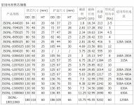
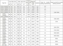
The following two charts are for a nanocrystaline transformer toroid cores, based on today's welding machines.
For unknown reason, I always thought, that soft switching isn't ideal for a regulated, adjustable power supplies ? How badly am I wrong ?
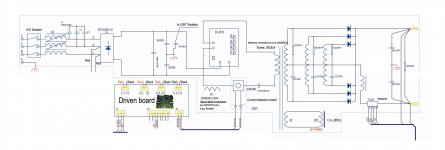
These rough schematics are just to illustrate the concept of the design.
Kind Regards
mark
I'm about to make my very first ever smps.
I have enough of practical knowledge, and quite a bit of theory, but all that is a self taught, so in order to make my smps happen, I need alot of help from outside world
The majority of help I need is to do with a calculating transformer core size, and all the associated key parameters.
The basic plan is:
8 - 30VDC
0 - 1000A
10kW
OCP, OVP, OPP, OTP,
10 turn pot for voltage
10 turn pot for current
Full bridge topology, initially based on two of SKM100GB128 or LUH75G1201 or something similar
Main transformer based on Amorphous / Nanocrystaline core, roughly 120/70/20 mm size toroid with just under 4cmsq of cross section (calculations needed)
Switching frequency around 20kHz
Multiple, center tapped secondary, and multiple output rectifier diode modules, something like MBRP400200, and individual output inductor per every center tap
Output filtration in LCLC fashion if needed to limit output voltage noise
Secondaries wound for a 5A/sqmm current density
Fully isolated control and driver circuit from power electronics (AC/DC/Pulse current transducers to keep pulse-by-pulse current control fashion, and TL431 with transoptor for voltage control)
Supply voltage 570VDC initially (rectified 415VAC 3Ph), and 800VDC in it's final stage when Active PFC will come to life (transformers primary will need to be rewired for that case I guess ?)
Initially hard switching with UC3846, but may need to go for soft switched, also based on UC3846
Due to my work, I have quite good resource of power electronics and such.
The real help I need is the amorphous / nanocrystaline cores info, and a general explanation of LLC soft switched SMPS's
Attached are pics of two driver boards. The smaller one is a UC3846 based, fully isolated hard switching driver, the bigger one is the same driver chip, but configured as a soft switching.
In both cases they need an external +/- 15VDC, PWM driving signal, and a primary side current feedback.
The soft switched one needs a 'zero shift' current transformer, and the hard switching one needs any DC / pulse current transducer.
So guys, I'm asking for a BIG favor from Your side, where do I start with power transformer ? And do I go hard or soft switching ?
The following two charts are for a nanocrystaline transformer toroid cores, based on today's welding machines.
For unknown reason, I always thought, that soft switching isn't ideal for a regulated, adjustable power supplies ? How badly am I wrong ?
These rough schematics are just to illustrate the concept of the design.
Kind Regards
mark
Attachments
-
 hard switch 1.jpg298.3 KB · Views: 271
 -
 hard switch 2.jpg289.1 KB · Views: 281
 -
 soft switch 1.jpg391.2 KB · Views: 264
 -
 soft switch 2.jpg376 KB · Views: 250
 -
 hard switching.jpg88.5 KB · Views: 254
 -
 soft switching LLC.jpg367 KB · Views: 190
 -
 Amorphous cores for welders.jpg323 KB · Views: 179
 -
 Amorphous cores for welders..jpg356.3 KB · Views: 104
I always prefer soft switching which greatly reduces switching stress.
The LLC-converter is preferable for fixed input, fixed output voltage. I designed several of them with pretty good results.
For a wide range voltage output I would go for the phase shifted ZVS full bridge - there are loads of tech papers at ti.com
And definitely I would NOT start developing smps with such a monstrous project.
And definitely I would NOT start developing smps with such a monstrous project.
+1 - 10kW does seem an awfully large power level to start out at.
- Status
- This old topic is closed. If you want to reopen this topic, contact a moderator using the "Report Post" button.