Hi !
i would like to understand more the requirements for mains noise filtering in digital equipment.
To explain a little better my situation i have a nice usb to spdif converter without any particular filter on the mains input.
The mains voltage goes directly to a toroidal voltage transformer (that i know is not the best filter in the world) and then to a normal power supply powering the pcb.
I really would like to add something upstream the transformer to suppress some noise that can be in the mains (i live in an industrial area and sound is better during holidays with factories closed).
So i am quite sure that there must be some noise in the mains.
And i cannot wait for holidays to enjoy decent sound ...
I woud much prefer a kit solution and made with passive parts.
Thanks a lot for any advice.
Kind regards, gino
Last edited:
You can buy mains filters.
They come in metal boxes that need to be electrically connected to the equipment Chassis.
They are also available as IEC input sockets with an integrated filter.
The filters should work both ways.
They attenuate cable born interference coming in from the Mains and they should attenuate interference created in the equipment and reducing what your equipment could put back into the Mains.
You can buy mains filters.
They come in metal boxes that need to be electrically connected to the equipment Chassis. They are also available as IEC input sockets with an integrated filter.
The filters should work both ways.
They attenuate cable born interference coming in from the Mains and they should attenuate interference created in the equipment and reducing what your equipment could put back into the Mains.
Hi and thanks a lot for the very helpful advice
I have one general question on them. I see that they are specified for high currents, like from 7A up.
Given that the current in my unit is very very low, around 0.1A, will they be equally effective also at this low current ?
And do you think that, as i think, they could be beneficial for overall sound in a digital equipment ?
Thanks a lot, gino
I keep a small stock of 1A, 3A and 6A IEC socket filters.
Just look at the retailer catalogues for the current rating you require.
BTW, the attenuating capability goes down as current rating goes up.
i.e. you get more attenuation of interference by using a correctly rated filter than you get from a too high rated filter.
Just look at the retailer catalogues for the current rating you require.
BTW, the attenuating capability goes down as current rating goes up.
i.e. you get more attenuation of interference by using a correctly rated filter than you get from a too high rated filter.
I keep a small stock of 1A, 3A and 6A IEC socket filters. Just look at the retailer catalogues for the current rating you require.
BTW, the attenuating capability goes down as current rating goes up.
i.e. you get more attenuation of interference by using a correctly rated filter than you get from a too high rated filter
Hi and thanks a lot for this very important advice. This reflects what i heard already. My idea would be to purchase some service manual of very good dvd players or similar and look what they use for the mains input filter.
I understand that also the diodes after the transformer are extremely critical
And i guess some kind of filtering should be used also there.
But i see this more tricky to carry-out on my unit.
Instead adding something before the transformer could be done more easily.
Thanks a lot again for confirming a very important point.
Regards, gino
I don't agree that the rectifier diodes are critical.
Are the PSUs in modern digital equipment, SMPS direct off the mains line, or via an isolating transformer to usable LV?
Actually i do not know. I have here this unit below, a usb to spdif converter, of which i would like to upgrade the power supply providing a DC clean power instead of connecting it to the mains
An externally hosted image should be here but it was not working when we last tested it.
The unit has almost no mains noise filtering and toroids are famous to let all the garbage through, while instead EI type are much better at blocking HF noise, so bad for digital.
the idea is to bypass transformer and diodes and to feed clean DC from an external good quality PS directly to the blue caps before the main voltage regulator.
In this way there will be another regulation stage before the one on the board, and noise reaching the circuit should be already very low.
In this way i hope to reduce the noise entering the unit from the power supply.
I have already a quite silent DC power supply to test.
Thanks, gino
Last edited:
This post might be worth considering:
http://www.diyaudio.com/forums/class-d/38199-ucd180-questions-35.html#post466003
Medical grade mains filters do not use Y caps to ground.
As far as low noise DC regulators there are many different to choose from, depends on your current/voltage needs. Example Analog Devices ADM7150 is capable of 800mA with ~1.0 µV noise. Texas Instruments TPS7A4700 1A, ~4 µV. Both can be sourced quite cheap. DIYINHK got kits for both but can't comment on quality.
This post might be worth considering:
http://www.diyaudio.com/forums/class-d/38199-ucd180-questions-35.html#post466003
Medical grade mains filters do not use Y caps to ground.
Hi and thanks a lot for the very interesting link. I will study it.
As far as low noise DC regulators there are many different to choose from, depends on your current/voltage needs. Example Analog Devices ADM7150 is capable of 800mA with ~1.0 µV noise. Texas Instruments TPS7A4700 1A, ~4 µV. Both can be sourced quite cheap. DIYINHK got kits for both but can't comment on quality.
Wow ... these are impressive figures indeed.
But i wonder if the comment about regulators being much less effective on HF noise applies also to these high end parts.
I have come to the conclusion that HF noise is the evil of digital.
The grainy, hazy, harsh sound could be due to some HF noise reaching the chips like clock and dac ...
In the meantime i have decide to replace the power supply.
I have bought a 40VA pcb mount transformer that i hope will have primary and secondaries separated (better filtering of mains noise), some schottky diodes and new Nichicon FG caps ...
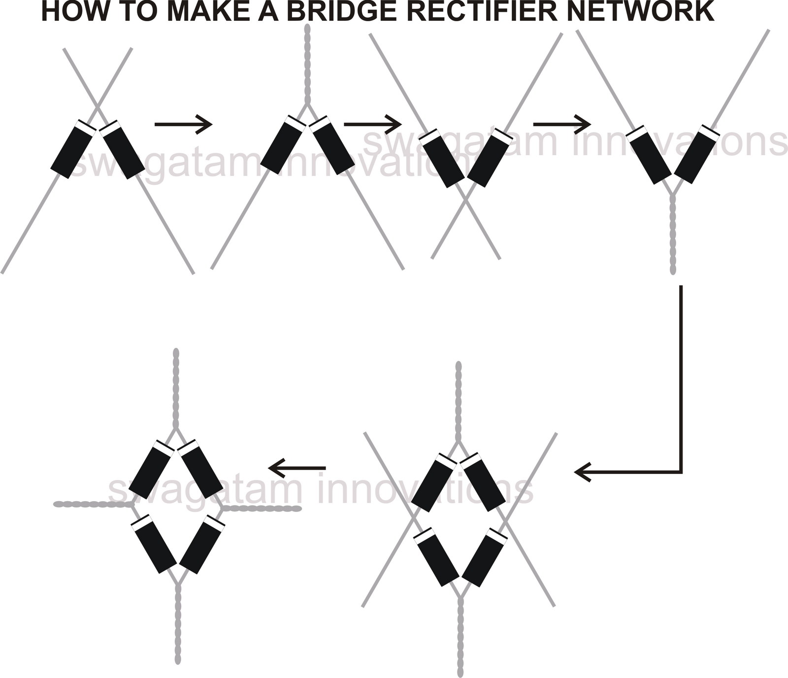
I will build a bridge with the schottky follow this nice procedure
I have one question.
Given the more VA of this trans, is it ok to use just one of the two secondaries and leave the other open ?
The total consumption of the unit will be less than 10VA i guess.
Thanks a lot again, gino
What part did you decide to replace?
It seems to have double regulated psu. First the 4 big caps followed by the first regulator(LT1963) that probably makes about 5V, then all separate parts have separate 3.3V regulator.
Then near the chip many local filter caps that supposed to remove the leftover HF noise.
Not sure you can make much improvement without seriously modifying the whole pcb.
Connect the two secondaries in parallel, same voltage double current capability compared to one secondary. It does not harm, the device only draws the current it needs.
Mains Voltage Power Transformers - delabs
One way to combat HF noise in the power supply is common mode filters, check out these designs:
http://www.diyaudio.com/forums/group-buys/264185-squeezebox-touch-psu.html
http://www.diyaudio.com/forums/power-supplies/273447-raspberry-pi-psu-tps7a8300-5v-2a.html
Product examples:
Common Mode Filters / Chokes | EMC Components | Products | TDK Product Center
DL? / PL? Series | Murata Manufacturing Co., Ltd.
What part did you decide to replace?
Hi ! thanks for the kind reply !
Just transformer, diodes and caps and stop.
I have bought one that should have separation between primary and secondaries, and so better filtering of mains noise.
Diodes Schottky ... and Nichicon FG series, 16V/2200uF (i have been told they are very good for low V applications)
It seems to have double regulated psu. First the 4 big caps followed by the first regulator(LT1963) that probably makes about 5V, then all separate parts have separate 3.3V regulator.
Then near the chip many local filter caps that supposed to remove the leftover HF noise.
Not sure you can make much improvement without seriously modifying the whole pcb
Yes ! the main first regulator is indeed a LT1963 (i guess it is a good one)
So in the end the real problem is to feed it with let's say 10VDC/1A very very clean ... just that ... let's do 1.5A to be on the safe side.I have bought some Nichicon FG 16V/2200uF to replace the stock ones ... not in the same league i guess of the FGs
the transformer secondaries feed 2 diode bridges and 2 caps each.
Everything is in parallel. The transformer is a 7V+7V/15 VA toroid.
I have bought a pcb mount encapsulated one that seems better and is
9V+9V/40 VA.
Just one secondary will be more powerful that the whole original transformer (i.e. 20VA vs. 15VA), so completely adequate.
So the idea is to use just one of the secondaries and leave the other open and unused ... i wonder if this will damage the transformer
Then i will make a bridge with the single Schottky ... i have seen on web how to twist them.
In this way i hope to achieve above all other things a better suppression of mains HF noise and less HF noise in general.
All the parts are better than the originals.
Thanks a lot again, gino
Last edited:
Connect the two secondaries in parallel, same voltage double current capability compared to one secondary. It does not harm, the device only draws the current it needs.
Mains Voltage Power Transformers - delabs
Hi and thanks a lot for the kind advice.
Can i use just one secondary ? it is more than enough with 20VA instead of the original 15VA total.
Leaving a secondary open will damage the transformer ? will increase noise ?
One way to combat HF noise in the power supply is common mode filters, check out these designs:
http://www.diyaudio.com/forums/group-buys/264185-squeezebox-touch-psu.html
http://www.diyaudio.com/forums/power-supplies/273447-raspberry-pi-psu-tps7a8300-5v-2a.html
Product examples:
Common Mode Filters / Chokes | EMC Components | Products | TDK Product Center
DL? / PL? Series | Murata Manufacturing Co., Ltd.
thanks a lot again. But i will need the weekend to read all.
I think i am quite close to close the issue with these additional info.
Again i just wonder if using only one secondary could damage the transformer or increase the noise.
That would simplify a lot.
Thanks again, gino
Does your USB-S/PDIF have transformer isolation on the S/PDIF output and/or isolation on the USB input?
If not then probably filtering its mains will have limited effect because a typical computer has a very noisy switching supply - the noise will 'leak' out over USB.
Hi and yes i think so because i have an usb adapter that cuts the power from the pc and the converter works anyway.
So my understanding is that the usb port does not need power from outside to work. Other units do not work with this adapter ... i have to connect it to an external PS.
Picture of the cable with adapter.
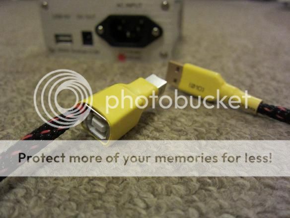
Thanks a lot, gino
Consider that the original transformer voltage was 7V AC, yours is 9V, meaning the first regulator will have to heat away about 3V plus DC voltage. Meaning roughly double the heat.
Check how hot it gets.
Put little ceramic caps (snubber) paralel to the diodes. Like 100pF-100nF. Not sure about the size. Smg like this.
This pic looks better")
Check how hot it gets.
Put little ceramic caps (snubber) paralel to the diodes. Like 100pF-100nF. Not sure about the size. Smg like this.
This pic looks better
")
Last edited:
Consider that the original transformer voltage was 7V AC, yours is 9V, meaning the first regulator will have to heat away about 3V plus DC voltage. Meaning roughly double the heat.
Check how hot it gets.
Hi and thanks. Do you mean that this could be an issue ?
i was not prepare to this ... i could burn the regulator ? The next voltage down is 6 ... i cannot find 7VDC transformer easily. I will look for another one of 8V ?
Put little ceramic caps (snubber) paralel to the diodes. Like 100pF-100nF. Not sure about the size. Smg like this.
This pic looks better
the problem with diodes is that are inside an integrated bridge extremely small
Bypassing them is very difficult.
For this i have bought some Schottky diodes to use. Those i could bypass much more easily.
Like i could bypass the ps caps as well.
Looking at the schematic ... do you think that that X-cap between live and neutral could be beneficial ? that i could place easily also myself.
Thanks again, gino
Last edited:
Simply disconnecting the two power wires and it still working doesn't mean there's necessarily isolation. Rather it means there's local power provided for the USB interface. The interference is carried down the screen of the USB cable which can't normally be disconnected as its needed to ensure the USB PHY 'sees' a common-mode voltage within its working range.
Simply disconnecting the two power wires and it still working doesn't mean there's necessarily isolation. Rather it means there's local power provided for the USB interface. The interference is carried down the screen of the USB cable which can't normally be disconnected as its needed to ensure the USB PHY 'sees' a common-mode voltage within its working range.
Hi and thanks for the explanation.
If i cut also the screen, leave only the two data wires and the converter works anyway that would mean that is isolated ?
i am willing to sacrifice a cable to do check this
Pc power is very dirty. Better to block it at pc level for sure.
Regards, gino
Hi and thanks. Do you mean that this could be an issue ?
i was not prepare to this ... i could burn the regulator ? The next voltage down is 6 ... i cannot find 7VDC transformer easily. I will look for another one of 8V ?
Can cause, but doesn't mean it will. Just don't forget to check it.
How hot it is now?
- Status
- This old topic is closed. If you want to reopen this topic, contact a moderator using the "Report Post" button.
- Home
- Amplifiers
- Power Supplies
- Mains filtering for a digital equipment.