Can cause, but doesn't mean it will. Just don't forget to check it. How hot it is now?
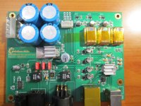
Well honestly i did not check at first. And now it is like in the attached picture below.
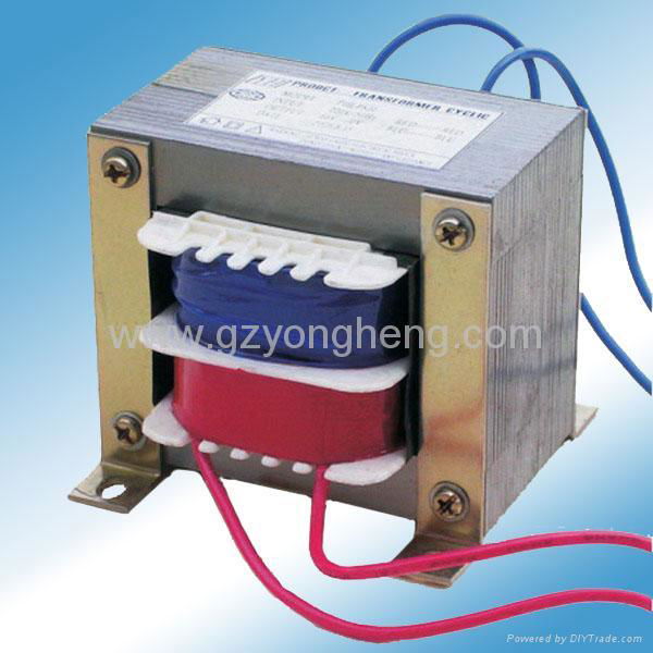
Problem is that the secondaries goes from 6+6 to 9+9 on ebay
i was not able to find 7+7 or 8+8
But i will look on mouser.com ... i like a lot Hammond transformer. Better, love them.
My dream machine use them ... so ...
problem is that even the dream machine does not have a usb input.
In my mind a very good usb to spdif converter will free me to use ANY at least decent pc around, with ANY OS, with ANY at least decent dac around.
A very firm point in the audio chain ... a very fundamental one indeed.
Attachments
Last edited:
First check with the one you have, then if it does get hot, then check for another. I think the first regulators load will go about 50-60%. Should be able to hadle. Don't think the whole thing consumes too much amp.
Hi and thanks again and sorry to take profit of your patience.
I am thinking to give up at the idea ... maybe i will just replace the stock caps in the ps with the Nichicon FG (maybe with a small by-pass)
and then experiment with some filters at the mains in.
last thing that i want is to fry the regulator
It is also very difficult to replace because it is smd.
I do not understand why components that can get quite hot are not built easy to heatsink. Better with an heatsink alredy attached.
Is this a massacre game ? they think to the end user ?
It is like a hammer with spikes on the handle. Form should follow function.
Thanks again, gino
Last edited:
The max input voltage for the LT1763 is 20V, max current out 500mA. Worst case dropout is ~450mV. Try to aim at the lowest voltage overhead needed to provide stable operation under worst case scenario, this will extend the life of the component. If the output voltage is 5V you only need ~6V input voltage.
Rough calculation:
[Transformer secondary voltage]*1.414 - [Diode voltage drop at 500mA] * [Worst case mains fluctuations +/- 10%].
Conservative calculation for a 6V transformer: (6*1.414)=8.484V - 1V (Schottsky bridge will be less drop, check datasheet) * 0.9 (Worst case mains fluctuation - 10%) = ~6.73. That will provide ~1.73 overhead voltage which is within safe limits for this regulator.
Side note: Check the regulator datasheet for overhead voltage graphs vs PSRR to determine optimum minimum overhead. The LT1763 does not provide this but other regulators sometimes does.
Last edited:
The max input voltage for the LT1763 is 20V, max current out 500mA.
Hi and thanks a lot for the precious information.
So this should mean that the actuall current draw of the circuit is lower than 0.5A ... very low consumption.
Because this regulator provide current for all the board.
Worst case dropout is ~450mV. Try to aim at the lowest voltage overhead needed to provide stable operation under worst case scenario, this will extend the life of the component. If the output voltage is 5V you only need ~6V input voltage.
Rough calculation:
[Transformer secondary voltage]*1.414 - [Diode voltage drop at 500mA] * [Worst case mains fluctuations +/- 10%].
Conservative calculation for a 6V transformer: (6*1.414)=8.484V - 1V (Schottsky bridge will be less drop, check datasheet) * 0.9 (Worst case mains fluctuation - 10%) = ~6.73. That will provide ~1.73 overhead voltage which is within safe limits for this regulator.
Side note: Check the regulator datasheet for overhead voltage graphs vs PSRR to determine optimum minimum overhead. The LT1763 does not provide this but other regulators sometimes does.
Thanks a lot again for all the advice and calculation.
But i dont understand why i find one ebay.com 6V and 9V but not 7 and 8.
For this kind of chip clearly 6V is low and 9V is too much.
And i guess this happens for all the similar regulators.
I will look again in the catalog anyway.
I will check ebay.co.uk ... they have also some strange things .. in UK.
But 9V is clearly too much.
I am sorry but i am thinking to give up at the idea ...
maybe i will just replace the stock caps in the ps with the Nichicon FG (maybe with a small by-pass)
and then experiment with some filters at the mains in (external ones).
last thing that i want is to fry the regulator
And also on the basis of your calculation it seems very delicate.
Thanks again, gino
Last edited:
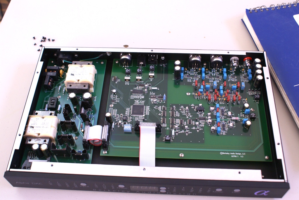
What is the output voltage on the regulator? If it's 5V out a 6V transformer is probably the best choice.
it is difficult to answer because this is the situation now ... i have removed the ps caps and waiting for the Nichicon FG
but now i see in the upper left corner of the pcb close to the diodes AC 6-10 V
Attachments
![IMG_0444[1].jpg](/community/data/attachments/439/439428-f7032871bb524a9c5df93c8f3ada21c0.jpg)
Alright probably 5V out then. Spending money on a new transformer wont give any results SQ wise unless the transformer you have now is faulty. Better save the money and spend them on a new better device ") . External low noise regulator will probably give you minimal gains but at least it's possible to use for other devices if you want.
. External low noise regulator will probably give you minimal gains but at least it's possible to use for other devices if you want.
. External low noise regulator will probably give you minimal gains but at least it's possible to use for other devices if you want.Alright probably 5V out then. Spending money on a new transformer wont give any results SQ wise unless the transformer you have now is faulty. Better save the money and spend them on a new better device
Originally my idea was to powered the unit with an external regulated lab grade power supply, this one here
http://www.komteh.hr/download/radio/mascot/acdc/719.pdf
to connect the output of this power supply to one of the big caps on the pcb (they are all 4 connected in parallel)
In this way i would have two stages of regulation ... in the external PS and on the board with the LT1763.
Used in range 1 Vout is 0-15VDC and quite clean also (ripple 0.3mV RMS).
This was the original idea ... then i messed up things.
Is this a sane idea ?
Thanks a lot again, gino
P.S. the device i can assure you has some potential for very good sound.
And also with different pc sources. It is well designed.
But of course if you know of something good with an usb input and a AES/EBU output i am very interested.
Not very expensive please.
Last edited:
A lab supply is very versatile, a few amps is not enough to supply power amplifiers but it's good for small equipment. I guess it depends on what you plan to use it for. If you live in an area with polluted mains opting for a medical grade filter with ADM7150/TPS7A4700 kit set to 6V would probably give you lower noise for this particular project. Question is how DIY you want to go and if it can be of value to other projects you might do in the future. Since the LT1763 is already quite low noise ~20µV and it supplies voltage regulators at the chips/clocks (what models?), adding another regulator can only get you so far... First try changing the caps, be weary of small snubbers sometimes they add oscillation at high frequencies. Then you can add a mains filter, see if you can hear improvement you can easily transplant the filter to other equipment if you want. Think carefully before you spend money on external supply...
A lab supply is very versatile, a few amps is not enough to supply power amplifiers but it's good for small equipment. I guess it depends on what you plan to use it for. If you live in an area with polluted mains opting for a medical grade filter with ADM7150/TPS7A4700 kit set to 6V would probably give you lower noise for this particular project. Question is how DIY you want to go and if it can be of value to other projects you might do in the future. Since the LT1763 is already quite low noise ~20µV and it supplies voltage regulators at the chips/clocks (what models?), adding another regulator can only get you so far...
First try changing the caps, be weary of small snubbers sometimes they add oscillation at high frequencies.
Then you can add a mains filter, see if you can hear improvement you can easily transplant the filter to other equipment if you want.
Think carefully before you spend money on external supply...
Hi and thank you sincerely for your kind and very valuable advice.
I will follow your directions and thanks also for the info about regulator (a good piece i understand) and the doubts about small caps for bypass.
New PS caps are on their way and next week i will receive them.
I will keep mods to a minimum. The risk to damage the unit is very high.
I would try some DIY similar projects ... but everything is smd these days
Thanks a lot again. You made me think rightly.
Kindest regards, gino
Good luck with the project. Please report back with results. I'm really interested in what difference the mains filter can have, actually thinking about making a DIY filter with coilcraft chokes and X2 cap.
Yes that is sure if i do not break everything
Problem with filters is that the ones off-the-shelf are usually for higher currents
This thing here should draw 0.1A at 230VAC max.
So they could be not very effective. A combination of chokes and caps is what i see in dacs and digital players.
I was thinking to look at some service manuals of dvd or cd player to get some idea on values and schematic.
But i will report anyway.
Thanks a lot indeed again.
Kind regards, gino
Breaking things is part of learning, just try not to
Low current draw is a good thing. Current rating is most likely where the coil(s) start to saturate or overheat. They are more effective at low currents + lower rated filters usually have better noise attenuation, check AndrewT's comments at the thread start. Remember avoiding Y caps to ground is probably best solution = medical grade filters.
Good idea, look at as many schematics other projects as possible for ideas to improve your own. When looking at schematics remember a component may have more characteristics than what is printed example a capacitor has ESR/ESL to take take into account check for BOM or pictures to identify the specific components to avoid unwanted effects.
Happy hunting
Hi and thanks a lot for the kind words and very valuable advice.
Just one idea ... placing a small film cap across the + and - directly on a diode bridge at its output could be beneficial to tame some diodes spike ?
I was thinking about a 0.1uf film cap of good quality.
Thanks again.
Regards, gino
Just one idea ... placing a small film cap across the + and - directly on a diode bridge at its output could be beneficial to tame some diodes spike ?
I was thinking about a 0.1uf film cap of good quality.
Thanks again.
Regards, gino
adding capacitance across the rectifier reduces the ringing frequency. You need a snubber to damp the circuit and minimise the ringing. A snubber is a resistor to absorb energy (and generates heat) when current passes across it.
Hi and thanks for the very helpful reply. So it could be beneficial ?
because the idea now
is to feed unregulated DC to the box.I am buying parts to assemble a very basic unregulated DC power supply: transformer > Schottky diodes > Sprague cap and send this DC to the internal regulator.
I believe that with a right selection of parts the quality of this unregulated DC will make the work for the on board regulator easier.
My main objective is to filter very well HF/RF noise from the mains.
I read a lot about this noise and i think it is a really bad thing to have.
I will have two different transformer to try ... but i could buy another one if necessary.
As i said the regulator on board is a LT1763.
The transformers i bought are a little high at 9V (the stock one is 7V).
If you have any suggestion for a transformer better suited i am all ears.
Mains filtering ability is a must. I would like to avoid filters on the input.
Thanks a lot indeed.
Kind regards, gino
P.S. my first choice is still the following (and i could place it quite far from the circuit to avoid EMI)
Last edited:
AndrewT: Do you have formulas or rule of thumb for optimal sizing?
Should one avoid very low ESR dielectics like polypropylene?
What setup is most efficient, seen several: one across each diode, across + -, across transformer secondaries or from each secondary to ground?
tomchr design very fine devices, this is his solution for +/- rail:
http://www.neurochrome.com/wp-content/uploads/2014/12/Power-86_BareBoard1200x800.jpg
Would like to clear this up, I have no good information on the subject
I am of the opposite persuasion........................ I would like to avoid filters on the input...................
I recommend RF attenuating filter at EVERY input and even at some of the outputs, (because many outputs can become inputs, eg power amp output is an input to the -IN pin of the amplifier).
Even TV aerials are now being sold with an RF attenuating filter to reduce the interference coming from mobile phones !
Many older TV aerials and masthead amplifiers have RF attenuating filters to reduce the interference from CB radio and other out of band signals.
Read the quasimodo threads and literature.AndrewT: Do you have formulas or rule of thumb for optimal sizing?
Should one avoid very low ESR dielectics like polypropylene?
What setup is most efficient, seen several: one across each diode, across + -, across transformer secondaries or from each secondary to ground?
.............
.................I have no good information on the subject
It seems that much of what I post is a regurgitation of what I have learned from this Forum, that other Members refuse to look for and refuse to read.
- Status
- This old topic is closed. If you want to reopen this topic, contact a moderator using the "Report Post" button.
- Home
- Amplifiers
- Power Supplies
- Mains filtering for a digital equipment.