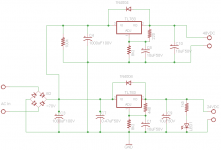
Hi all, I've been learning and trying different PSU configurations . Check the following schematics (caps at the output of 783 are actually 63V, my bad). I got both to work fine on boards (allelujah!) but I have a couple questions:
1. I'd like to know if one is preferable over the other. It is a 48V transfo from which I need 48VDC and 24VDC. This will power audio preamp
2. Why is the voltage reading ~51V at the output of the 24V if it's unloaded?
1. I'd like to know if one is preferable over the other. It is a 48V transfo from which I need 48VDC and 24VDC. This will power audio preamp
2. Why is the voltage reading ~51V at the output of the 24V if it's unloaded?
Attachments
Last edited:
1) The circuit with two TL783's. If you take a look at the datasheet of the LM7824, then you'll find that its absolute maxiumum rated input voltage is 40 V. A 7824 will (eventually) not survive on 48 V.
2) The 24 V output of which circuit? Edit: if it's the circuit with the two '783s, you do know that these need a min. load of at least 15 mA? The adjust resistors will draw about 2.8 mA from the output, but what does the LED draw? With 1k5 in series, it might be a tad low...
2) The 24 V output of which circuit? Edit: if it's the circuit with the two '783s, you do know that these need a min. load of at least 15 mA? The adjust resistors will draw about 2.8 mA from the output, but what does the LED draw? With 1k5 in series, it might be a tad low...
Last edited:
In that case I guess the minium load requirement of the TL783 is not met.
If you use a standard red LED with a Vf of 2.2 V and a current of 20 mA for LED1, then a 1 k series resistor is close enough. With that, I would expect the output to be always in regulation.
If you use a standard red LED with a Vf of 2.2 V and a current of 20 mA for LED1, then a 1 k series resistor is close enough. With that, I would expect the output to be always in regulation.
Last edited:
Both are doable. This kind of thing is decided based on what material you have vs what you need to achieve e.g. how clean you want the rails how much current you want how much heat can you handle.
Current generation computer psu grab the minor rails off the main 12V rail for higher efficiency and lower cost. This is doable if he minor rail current is low compared to the main rail. The minor rail also gets better quality. Downside is the current drawn comes from the output of the main rail and you're using linear regulation so if your output draws 1A 48V and 1A 24V there is 2A through your 48V regulator.
If you opt to have transformer output go straight to 24V, you can add a pre regulator with a transistor and some parts to drop some voltage while providing a bit of cleanup before reaching the 7824.
Alternatively, get a 48V transformer with center tap in other words a 24-0-24 transformer. To get 48V you wire it with your bridge rectifier. To get 24V you wire it as a full wave center tapped rectifier. Note that if you do try to generate 24V alongside 48V like this, you cannot connect their "gnd" together, so depending on your circuit this may or may not be allowed. What is your circuit anyway?
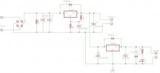
Isn't there a lot of heat dissipation with the 2 tl783 configuration? The input is ~70V for each regulator. Could I run the 48V output from one 783 to the input of the other so to have 48V IN and 24V out?
That really depends on how much current your preamp is going to draw from both rails. Presumably, that's pretty low.
Example:
Vin = 70 V
Iout48 = 100 mA (total of load + regulator and adj. resistors)
Iout24 = 100 mA (total of load + regulator and adj. resistors + LED)
Option 1, two TL783s connected to the bridge rectifier:
Pdiss48 = 0.1*(70-48) = 2.2 W
Pdiss24 = 0.1*(70-24) = 4.6 W
Ptotal = 6.8 W
Option 2, two TL783s cascaded:
Pdiss48 = (0.1+0.1)*(70-48) = 4.4 W (0.1 A drawn by the 48 V load + 0.1 A drawn by the 24 V cicruit+load).
Pdiss24 = 0.1*(48-24) = 2.4 W
Ptotal = 6.8 W
In this example, option 2 shares the dissipation between both regulators slightly better but in your application it will depend on the actual currents. Find out what those are and recalculate the dissipation in both regulators with both options and see what shares them the most even.
Last edited:
And just to satisfy my curiosity some more calculations with uneven loads:
Iout48 = 50 mA
Iout24 = 150 mA
Option 1:
Pdiss48 = 0.05*(70-48) = 1.1 W
Pdiss24 = 0.15*(70-24) = 6.9 W
Ptotal = 8.0 W
Option 2:
Pdiss48 = (0.05+0.15)*(70-48) = 4.4 W
Pdiss24 = 0.15*(48-24) = 3.6 W
Ptotal = 8.0 W
Option 2 gives far better share of dissipation.
And the other way around:
Iout48 = 150 mA
Iout24 = 50 mA
Option 1:
Pdiss48 = 0.15*(70-48) = 3.3 W
Pdiss24 = 0.05*(70-24) = 2.3 W
Ptotal = 5.6 W
Option 2:
Pdiss48 = (0.15+0.05)*(70-48) = 4.4 W
Pdiss24 = 0.05*(48-24) = 1.2 W
Ptotal = 5.6 W
Now option 1 gives far more equal share of dissipation.
Personally I won't be bothered by the uneven distribution of power. Not when I prefer to do overkill on cooling and if the load used and the device used is different (<-- since this affects internal thermal resistance, and consequently junction temperature even at the same external heatsink temperature) I'll just go for the one that is easier to build. Or if you're going for cheaper to build, then have both regulators connected straight to rectifier - so you won't waste the current capacity of the 48V and you can buy a cheaper part. Pre-regulators are a good source of voltage drop and transistors are cheaper than ICs.
- Status
- This old topic is closed. If you want to reopen this topic, contact a moderator using the "Report Post" button.
- Home
- Amplifiers
- Power Supplies
- Should I go off the Bridge or off the regulated supply?