Hi jitter,
It looks like the turn off of the rectifiers is riding straight through the Voltcraft. maybe even getting to the voltage reference. This is what I suspected the problem could be. I'm looking at the approximate area where the diodes stop conducting, which generates both a voltage and current oscillation (damped as shown). If you wanted to improve that little smelly (") ) Voltcraft, a little attention in those areas might cure it of this evil. Running the reference and regulation circuits from their own power supply (using the same transformer) might really help the poor little thing to make you a happier guy. It's low current, so not expensive to throw together.
) Voltcraft, a little attention in those areas might cure it of this evil. Running the reference and regulation circuits from their own power supply (using the same transformer) might really help the poor little thing to make you a happier guy. It's low current, so not expensive to throw together.
I wish mine did. I had / have a USB DSO 2250 off Eeekbay. It worked okay for a while, and one day the trace for ch 1 was railed positive with nothing connected. The only thing I could think of was the possibility that I killed it looking at a power supply. It worked fine when I turned it off the last time. Maybe it was just a crappy DSO.
If anyone has a schematic for this thing, I would love to fix it. It wasn't perfect, but very useable for some things, and it didn't take any room up (big plus). I actually liked it for what it did well.
These Philips scopes had a better trace than the Tektronix I looked at. Sorry - Sony-Tektronix. No way was I going to get involved with a Sony. The Tek sales guy could see clearly how substandard the Tek display was. Agilent was fine, just DSO and I needed an analog scope (or a million bucks to buy the scope that looked analog!). Philips was one of the few that weren't Japanese. I already had some of the Japanese scopes, and they break down too often. (Leader)
-Chris
It looks like the turn off of the rectifiers is riding straight through the Voltcraft. maybe even getting to the voltage reference. This is what I suspected the problem could be. I'm looking at the approximate area where the diodes stop conducting, which generates both a voltage and current oscillation (damped as shown). If you wanted to improve that little smelly (
) Voltcraft, a little attention in those areas might cure it of this evil. Running the reference and regulation circuits from their own power supply (using the same transformer) might really help the poor little thing to make you a happier guy. It's low current, so not expensive to throw together.Yes, exactly. We were taught by math people it would seem.With "Y1" and "Y2" I take it you mean channels A and B (or 1 and 2) of a scope.
Yes But it is a starter 'scope. At the low end, the best scope is analog.This thing has a worhtless triggering circuit, and seems to miss the narrow peaks most of the time
You know? It is close to the design of the PM3070 around the screen. The trace looks better today as you pointed out. Anyway, I agree with you, this is a nice old 'scope well worth keeping.The photos will have revealed the model.
Probably bad solder joint. No surprises there.However, sometimes trace intensity seems to abruptly drop to about half of what's normal.
No, you need some contact cleaner on the slip ring and fingers (only - not the carbon track). Apply with a fine dripper or a syringe directly onto the slip ring around the center. It doesn't take much! No sprays allowed.I would have thought that any oxidation would have been scraped off by now, but it doesn't seem to matter
From servicing mine, almost every cap is probably done. I used an HP 4263A LCR meter for this. Since my power supply is a switcher (not sure about yours), I tested the capacitors at 1 KHz. Things get ugly for electrolytic capacitors when the frequency goes up. The new parts tested much better, and I installed better makes of 105 °C rated parts. The originals were only 85 °C. Since all of mine were bad, if your scope uses a switching power supply, yours very likely are also well worn.I did measure the electolytics with an ESR meter, and they seemed to be just fine.
These specifications look pretty good. You have no worries I don't think. Just get out of the habit of using the X1 position on your probes. It's a bad habit. Use actual cables when you work direct so you never have the most terrible surprise. Use silicone into the X1 space to lock the probes into X10. The silicone can be pulled out if needed, but you shouldn't ever have to question what position your probes are in.CAT I 300 Vrms, CAT II 100 Vrms, transient overvoltage 1000 Vpk
I wish mine did. I had / have a USB DSO 2250 off Eeekbay. It worked okay for a while, and one day the trace for ch 1 was railed positive with nothing connected. The only thing I could think of was the possibility that I killed it looking at a power supply. It worked fine when I turned it off the last time. Maybe it was just a crappy DSO.
If anyone has a schematic for this thing, I would love to fix it. It wasn't perfect, but very useable for some things, and it didn't take any room up (big plus). I actually liked it for what it did well.
My scope sounds like it was older than yours! They used mostly axial to save on vertical height. You should see if you can grab one of those PM3070's. It probably just needs the power supply rebuilt.All radial electrolytics and only through hole in the '3208.
These Philips scopes had a better trace than the Tektronix I looked at. Sorry - Sony-Tektronix. No way was I going to get involved with a Sony. The Tek sales guy could see clearly how substandard the Tek display was. Agilent was fine, just DSO and I needed an analog scope (or a million bucks to buy the scope that looked analog!). Philips was one of the few that weren't Japanese. I already had some of the Japanese scopes, and they break down too often. (Leader)
-Chris
Hi peufeu,
-Chris
Exactly, but I wanted to see where his hash was coming from under normal operation.For testing the transient response of a power supply or decoupling caps, you need something that will generate a current step.
No, a BJT is easier. You have to deal with gate charge with the Mosfet, and it is worse at higher currents. Switching speed is your devil here.It should also be as dumb as possible : A switching MOSFET is nice
I wish. You need to supply a very stiff driver with high current capability in order to hide the gate charge effects, and it works going on and going off. So both charge and discharge need to be driven. Run from it's own internal power so that effects from the PS under test do not contribute anything beyond what you are studying.At this point, any settling effect will come entirely from the power supply under test, so you really know what you're measuring. It is nice to know you can rely on your instruments !
-Chris
Hi jitter,
It looks like the turn off of the rectifiers is riding straight through the Voltcraft. maybe even getting to the voltage reference. This is what I suspected the problem could be. I'm looking at the approximate area where the diodes stop conducting, which generates both a voltage and current oscillation (damped as shown). If you wanted to improve that little smelly (
I'm not sure I want to modify this PSU. It's really a mess of wires in there and every wire is soldered, there's not a connector to be found. Added to this is the fact that I can't find any schematics of this PSU and I'm not really keen on reverse engineering it. This pic might give you an idea.
Here's a closeup of one of the channels. I'm assuming that IC101, visible in the lower right corner of the pcb, is the reference as it's an LM336. The diode noise and ripple do get there, but only if both (parallelled) channels are running CC mode. With one channel into CV mode, it's gone.
Because of the cheap look I was surprised to find well known semiconductor brands in there instead of Chinese clones. Also all electrolytics are from Samwah and not some obscure Chinese brand no one has ever heard of.
There's even an EMI filtered IEC mains input.
No, you need some contact cleaner on the slip ring and fingers (only - not the carbon track). Apply with a fine dripper or a syringe directly onto the slip ring around the center. It doesn't take much! No sprays allowed.
OK, I guess that's worth the effort after all. And I 'll look over the BNC for a cracked solder joint.
From servicing mine, almost every cap is probably done. I used an HP 4263A LCR meter for this. Since my power supply is a switcher (not sure about yours), I tested the capacitors at 1 KHz. Things get ugly for electrolytic capacitors when the frequency goes up.
The new parts tested much better, and I installed better makes of 105 °C rated parts. The originals were only 85 °C. Since all of mine were bad, if your scope uses a switching power supply, yours very likely are also well worn.
The PSU is linear in the PM3208. ESR measured fine, even on 100 kHz.
Just get out of the habit of using the X1 position on your probes. It's a bad habit. Use actual cables when you work direct so you never have the most terrible surprise. Use silicone into the X1 space to lock the probes into X10. The silicone can be pulled out if needed, but you shouldn't ever have to question what position your probes are in.
Good advice, thanks.
My scope sounds like it was older than yours! They used mostly axial to save on vertical height.
Or perhaps of a different design... The PM 3208 looks like its design may actually not have been done by Philips. Most parts are of Japanese manufacture rather than Philips' own. The CRT carries a Matsushita sticker and the scope was made in Korea.
Googled some pics of the PM3070, I see the typical transparent blue Philips axial caps you mentioned and the solid light blue radial caps. Also quite a few Philips semiconductors. Now this would probably be designed and built by Philips (it also says "Made in Holland" on the back, that could quite possibly have been here, in the city I now live in).
Hi jitter,
You could move the four rectifiers onto the chassis using a 6A + bridge. That takes the heat off the main PCB. Your LM336 is probably fed by a resistor. Replace that with a CCS built from a TO-126 transistor and a 3 mm red LED put into the center hole, and a couple resistors. Cheap and very cheerful! This change alone would completely transform that little supply.
The wiring isn't the easiest to deal with, but it is a lot better than most I have had to work in. You just don't feel like working on it. That isn't a bad thing as I have that same issue on some things myself.
-Chris
You could move the four rectifiers onto the chassis using a 6A + bridge. That takes the heat off the main PCB. Your LM336 is probably fed by a resistor. Replace that with a CCS built from a TO-126 transistor and a 3 mm red LED put into the center hole, and a couple resistors. Cheap and very cheerful! This change alone would completely transform that little supply.
The wiring isn't the easiest to deal with, but it is a lot better than most I have had to work in. You just don't feel like working on it. That isn't a bad thing as I have that same issue on some things myself.
That's good news. I am very happy you don't have the issues I did with mine.The PSU is linear in the PM3208. ESR measured fine, even on 100 kHz.
Well, there is an iffy connection somewhere in there.And I 'll look over the BNC for a cracked solder joint.
You are probably right on that score. Korea can make really good stuff if they want to.The PM 3208 looks like its design may actually not have been done by Philips.
The folks at Matsushita make really good stuff (except for stereos). Everything else they make is great stuff.The CRT carries a Matsushita sticker and the scope was made in Korea.
-Chris
Hi Chris,
Thanks for the advice. I'm not sure yet i want to leave it alone or modify it...
Not really, no. But I am thinking of buying a more precise PSU, and maybe, if I feel like it, I might tinker around with the Voltcraft. Maybe even completely reverse engineer it... who knows?
What were the issues? We still have one at work that I wouldn't be surprised will be "retired" soon... maybe I can have it if no one else is interested...
Sorry if this is going a bit off topic...
Hi jitter,
You could move the four rectifiers onto the chassis using a 6A + bridge. That takes the heat off the main PCB. Your LM336 is probably fed by a resistor. Replace that with a CCS built from a TO-126 transistor and a 3 mm red LED put into the center hole, and a couple resistors. Cheap and very cheerful! This change alone would completely transform that little supply.
Thanks for the advice. I'm not sure yet i want to leave it alone or modify it...
The wiring isn't the easiest to deal with, but it is a lot better than most I have had to work in. You just don't feel like working on it. That isn't a bad thing as I have that same issue on some things myself.
Not really, no. But I am thinking of buying a more precise PSU, and maybe, if I feel like it, I might tinker around with the Voltcraft. Maybe even completely reverse engineer it... who knows?
That's good news. I am very happy you don't have the issues I did with mine.
What were the issues? We still have one at work that I wouldn't be surprised will be "retired" soon... maybe I can have it if no one else is interested...
Sorry if this is going a bit off topic...
Hi jitter,
Yes, we are off into the weeds on this. Sorry for all if this is too off topic.
The issues with the PM-3070 would mostly be a failure to turn on. Any other funny behaviors very probably can be traced back to the capacitors on the power supply PCB.
If you can get that PM 3070, it will serve you very well. Fingers crossed!
For the Voltcraft, I was merely suggesting a couple small changes that would make a big difference to this unit. I wouldn't completely redo it. Just improve performance to enable it to serve you in the future as a nice little power supply. The rectifier is to halt heat damage on the PCB, so preventative in nature. The CCS should directly improve the problems you noted. Check that your DC levels aren't dropping too far under load as well.
-Chris
Hi jitter,
Yes, we are off into the weeds on this. Sorry for all if this is too off topic.
The issues with the PM-3070 would mostly be a failure to turn on. Any other funny behaviors very probably can be traced back to the capacitors on the power supply PCB.
By any chance accompanied by a high piched buzz? I tried to power it up today (it's actually not a PM 3070 but a PM 3355) and that's all I got...
If you can get that PM 3070, it will serve you very well. Fingers crossed!
I did lift the cover... and then put it back on again. Man, are these things filled to the brim.
But we also have a Fluke PM 3385 which is in fine working condition, and still annually calibrated. I'd like that one, please
.For the Voltcraft, I was merely suggesting a couple small changes that would make a big difference to this unit. I wouldn't completely redo it. Just improve performance to enable it to serve you in the future as a nice little power supply.
I didn't plan on redoing it completely, but before I do any mods, I'd like to know what I'm working on. I don't like working on electronics without any schematics (unless it's something blatantly obvious).
The rectifier is to halt heat damage on the PCB, so preventative in nature. The CCS should directly improve the problems you noted. Check that your DC levels aren't dropping too far under load as well.
Thanks for the sensible advice.
Hi jitter,
-Chris
Certainly. Sounds like a switch mode PS trying to start to me.By any chance accompanied by a high piched buzz?
Yes, go for both. If you can fix the PM3355, maybe it could help someone else. It can't do that from the trash bin. I desperately hate to see test equipment hitting the garbage can.PM 3385
Now you can see why there are heat problems with them.Man, are these things filled to the brim.
So do I.but before I do any mods, I'd like to know what I'm working on.
Well, that is a perfect world. Sometimes we just have to recognize a little part and work on that. But certainly have a look for service information. #1 spot to check is with the manufacturer.I don't like working on electronics without any schematics (unless it's something blatantly obvious).
-Chris
Hi shredhead,
Thanks for being a cool ModI'm a grumpy old technician!
-Chris
Not true, you're just old 😁
Jan
Hi jitter,
Yes, we are off into the weeds on this. Sorry for all if this is too off topic
Please continue, I've been reading with interest. My analog Tektronix from the early half of the 80's is messed up and I have to mend it at some point so I am very much interested in how this goes with Jitter's Philips, I hope you're able to fix the problem.
I'll probably post a pic or two of the problem with mine to get your opinions on it a little bit later.
Last edited:
We were talking about different pieces of equipment here, so to clear things up:
- the Voltcraft PSU is working fine, but I might upgrade it a little some time in the future;
- my Philips scope (PM 3208) is functioning correctly most of the time, but needs the contacts in the swicthes and selectors cleaned;
- the Philips at work (PM 3355) is dead but not mine to tinker with (might be if they decide to scrap it and I get dibs on it when they do, but there are more people keen on taking it home);
- the Fluke PM 3385 at work is in fine working condition, but isn't going to be scrapped any time soon as it's still in the calibration programme.
So unfortunately right now there isn't really anything interesting going on...
@shredhead: maybe you could start a topic in the Equipment & tools section?
I know this is not the right place for this but I just wanted to get your take on it while we were on the topic of scopes.
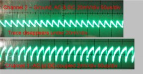
I got a used Tektronix 2213 and this is a pic of it with no input connected. Channel 1 seems to work ok, it shows what input you give it but this pic shows some kind of noise when it is turned to the highest sensitivity.
Channel 2 seems to be dead. It only shows what is in the picture or no trace at all regardless of the input.
Is this what happens when you fry the front end on a scope? Have you guys ever messed with fixing that kind of thing? I have the service manual http://www.hellspark.com/dm/ebench/tools/Analog_Oscilliscope/tektronix_2213_service.pdf
and plan on taking a crack at fixing it but I want to wait until I get my new scope.
Attachments
That Tek seems, at first glance, quite similar to my Philips. Apart from the colour, the bezel and filter are the same. Also, the form factor seems to be the same. The innards are a different story, though, but I wouldn't be surprised if somewhere along the design or manufacturing stages paths crossed...
Perhaps the noise in the first channel is cross talk from the second, dead, channel, and maybe that's why you can only see it with CH 1 on the most sensitive setting. CH 1 and CH 2 seem to show the same frequency.
Other than that, I really wouldn't know where to start with a scope, other than the usual place to start: PSU voltages. I believe Dave Jones actually calls that a law: "Thou shalt measure voltages!".
On second thought, perhaps it is better to move this to the Equipment and tools section. I expect there's more chance of positive feedback. Someone like Mooly, e.g., seems to have more experience repairing scopes than I do, and he seems to be in that section a lot...
Small correction: the Fluke I was talking about earlier is a PM 3382, not 3385.
Last edited:
Perhaps the noise in the first channel is cross talk from the second, dead, channel, and maybe that's why you can only see it with CH 1 on the most sensitive setting. CH 1 and CH 2 seem to show the same frequency.
Yeah, that makes a lot of sense. Thanks jitter. While I was inside I did a quick check on voltages and they looked within spec. I guess there's just no way around ripping this thing's front end apart and testing each component.
I'll wait until I get a trustworthy scope to try to fix this one and then I'll be sure to post in the tools section.
I just started a new thread on oscilloscopes. Perhaps we can continue the search for the cause of the dead channel on you Tek there?
See ya.
See ya.
Hi Jan,
I hear bookzine #9 is out "Linear Audio publishes Volume 9". I'm looking forward to it big time!
Folks, have a look at this web site. I will say that these "bookzines" are more than well worth the money. Shameless plug for a good old friend.
-Chris
There is no escape from those who know you well. Ya got me there sir!Not true, you're just old 😁
I hear bookzine #9 is out "Linear Audio publishes Volume 9". I'm looking forward to it big time!
Folks, have a look at this web site. I will say that these "bookzines" are more than well worth the money. Shameless plug for a good old friend.
-Chris
- Status
- This old topic is closed. If you want to reopen this topic, contact a moderator using the "Report Post" button.
- Home
- Amplifiers
- Power Supplies
- What does preamp PSU oscillation look like for linear regulators?