@OlegSH:
"Is there special reason to have a cut out rectangle in the GND on the bottom side?"
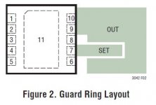
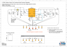
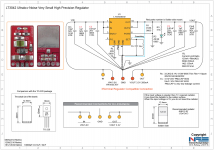
Yes, the datasheet writes (see picture too):
"Minimize board leakage by encircling the SET pin with a guard ring operated at a potential close to itself — ideally tied to the OUT pin. Guarding both sides of the circuit board is recommended. Bulk leakage reduction depends on the guard ring width. Leakages of 100nA into or out of the SET pin creates a 0.1% error in the reference voltage. Leakages of this magnitude, coupled with other sources of leakage, can cause significant errors in the output voltage, especially over wide operating temperature range. Figure 2 illustrates a typical guard ring layout technique."
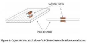
"You can skip the caps on the back side of the PCB entirely..."
There is a noise cancelling methode if you place the capacitors on the both side of the boards, see picture and How to reduce acoustic noise of MLCCs in power applications - Power House - Blogs - TI E2E Community.
@canvas:
Susumu RG semms to be good and has 1206 package too...")
"Is there special reason to have a cut out rectangle in the GND on the bottom side?"
Yes, the datasheet writes (see picture too):
"Minimize board leakage by encircling the SET pin with a guard ring operated at a potential close to itself — ideally tied to the OUT pin. Guarding both sides of the circuit board is recommended. Bulk leakage reduction depends on the guard ring width. Leakages of 100nA into or out of the SET pin creates a 0.1% error in the reference voltage. Leakages of this magnitude, coupled with other sources of leakage, can cause significant errors in the output voltage, especially over wide operating temperature range. Figure 2 illustrates a typical guard ring layout technique."
"You can skip the caps on the back side of the PCB entirely..."
There is a noise cancelling methode if you place the capacitors on the both side of the boards, see picture and How to reduce acoustic noise of MLCCs in power applications - Power House - Blogs - TI E2E Community.
@canvas:
Susumu RG semms to be good and has 1206 package too...
Attachments
Understood about the guard ring idea.
I did not know about mechanical noise cancellation if parallel capacitors are places on the opposite sides of the PCB. I'll note this trick for the future.
General comment: placing the LDO reg on the adapter will suffer from increased noise and voltage error anyways due to added leads impedance, IMO. I think all this ultra-low noise numbers are only achievable if the reg is placed near to the power pins of the device it supplies and if it shares same GND plane with it too.
Regards,
Oleg
I do care about two things on LT3042. The first would be the support of fast-start up feature. (Need PGFB, and no I-limit resistor)
What values should I use for PGFB resistors?
(Datasheet describes it a little bit difficult...)
What values should I use for PGFB resistors?
(Datasheet describes it a little bit difficult...)
It was stated on page 12 from datasheet.
Power good threshold = 0.3V • (1 + RPG2/RPG1)
So: if I want to have good noise rejection below 100Hz, than I need big (up to 22uF) SET capacitor.
Large SET capacitor means anyway an increased start-up time, so I need the PGFB resistors to activate fast start-up function.
I leave PG output floated because I don't need it. It is uninteresting for me the "power good threshold" voltage. All I need is fast starting-up...
What now?
Large SET capacitor means anyway an increased start-up time, so I need the PGFB resistors to activate fast start-up function.
I leave PG output floated because I don't need it. It is uninteresting for me the "power good threshold" voltage. All I need is fast starting-up...
What now?
Last edited:
I think I understand...
I can determine the output voltage level, until the fast start-up (2mA ref. current) should be activated. For example, if I need 5V regulated voltage, I should set the "PGT" value to 4,5 V or so...
Yes. Fast start-up will make v-out to pass PG threshold asap. Otherwise, it may take more than 0.5 sec to reach desired output voltage which could be a problem on some circuits, e.g. Ian's XO board.
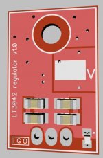
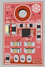
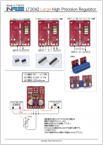
So, my final version.
And like interestingness some PCBs from China...
And like interestingness some PCBs from China...
Attachments
-
 LT3042_3Dfront_3.JPG55.2 KB · Views: 955
 -
 LT3042_3Dback_3.JPG69.9 KB · Views: 940
 -
 20160528_150102.png487.6 KB · Views: 480
 -
 20160528_150024.png572.4 KB · Views: 500
 -
 20160528_150010.png471.7 KB · Views: 511
 -
 20160527_033148.png404.1 KB · Views: 481
 -
 20160527_033055.png321.6 KB · Views: 602
 -
 20160527_032958.png606 KB · Views: 1,024
 -
 20160530_142516.png537.4 KB · Views: 574
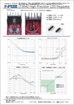
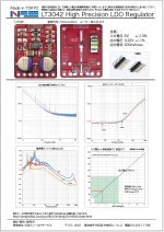
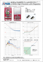
There is no magic. If you use the LT3042 according to the
data sheet, it will perform like in the data sheet. Stay away
from arbitrary improvements. If you increase the output
capacitor for example, there will be a noise peak, albeit above
the audio range. Use thin film resistors, not thick film, but
that is only important for low frequencies. (1/f)
Here is a test implementation right from the data sheet with
an external power transistor. The measured noise density plot is
the picture on the left or right. The coax attenuators are only
there to fix the small board for the photo. +6dB is 2nV/rt Hz.
< Lt3042_DH44 | Low noise regulator consisting of LT3042 and D… | Flickr >
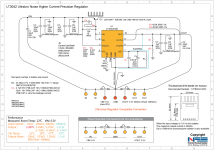
If you want to home-etch it, the layout is not a secret.
There is a 1:1 .pdf with a few of them, but there are other
test circuits added to make a full EuroCard (100*160mm)
cheers, Gerhard
data sheet, it will perform like in the data sheet. Stay away
from arbitrary improvements. If you increase the output
capacitor for example, there will be a noise peak, albeit above
the audio range. Use thin film resistors, not thick film, but
that is only important for low frequencies. (1/f)
Here is a test implementation right from the data sheet with
an external power transistor. The measured noise density plot is
the picture on the left or right. The coax attenuators are only
there to fix the small board for the photo. +6dB is 2nV/rt Hz.
< Lt3042_DH44 | Low noise regulator consisting of LT3042 and D… | Flickr >
If you want to home-etch it, the layout is not a secret.
There is a 1:1 .pdf with a few of them, but there are other
test circuits added to make a full EuroCard (100*160mm)
cheers, Gerhard
He is using +60dB preamp in front of the Analog Discovery.
"http://designideas.cocolog-nifty.com/blog/2016/05/lt3042-psrr-9ce.html"
"http://designideas.cocolog-nifty.com/blog/2016/05/lt3042-psrr-9ce.html"
I also used a 50-80 dB preamp in front of an Agilent 89441A Fourier analyzer.
After the preamp it is no longer critical. A sound card might also work.
Power the preamp from local NiMH batteries, you'll have ground loop problems
otherwise.
An AD797 gets you to 1 nV/rt Hz, averaging over 4 of them in parallel results
in 0.5 nV/rt Hz. That is better than needed for the LT3042. You can easily
see the thermal noise of a 60 Ohm resistor versus a short circuit.
60 Ohms delivers 1 nV/rt Hz at room temperature, nice for reality checks & calibration.
You do not even need to know the EXACT gain of your preamp/ADC.
I did use this one
< http://www.hoffmann-hochfrequenz.de/downloads/lono.pdf >
but with 20*10uF foil caps in the input. For frequencies below 50 Hz
it takes huge electrolytics / wet tantals that are unpleasant to handle.
The ceramic caps also worked for me, although they are disdained by many.
regards, Gerhard
Last edited:
He is using +60dB preamp in front of the Analog Discovery.
"http://designideas.cocolog-nifty.com/blog/2016/05/lt3042-psrr-9ce.html"
I was under the impression that Analogue Discovery included necessary circuits to measure voltage noise density. It would make sense if he designed the jig by himself.
I did use this one
< http://www.hoffmann-hochfrequenz.de/downloads/lono.pdf >
but with 20*10uF foil caps in the input. For frequencies below 50 Hz
it takes huge electrolytics / wet tantals that are unpleasant to handle.
The ceramic caps also worked for me, although they are disdained by many.
regards, Gerhard
Your preamp by ten AD4898 is excellent. Parallel DAC and ADC are popular technique now. But I have never imagined parallel Opamp! Paralleling in an analog domain works well like calculation in a digital domain. Even 0.22nV/rtHz can be done by this method. I highly appreciate your project.
Hi
I am interested in the PCB.
Hi,
would you like to have the CAD files or have some pieces from the manufactured PCBs?
Hi,
would you like to have the CAD files or have some pieces from the manufactured PCBs?
Hi,
One or two pieces of the PCB.
- Home
- Amplifiers
- Power Supplies
- Yet another ultra low noise high PSRR LDO - LT3042