Ales,
what is planned output current from your board? is it limited only by transistor?
Thanks
D.
Maxmim output current is 1.5A, it is limited by LT3042.
Hi,
LT has updated the LT3042 Model regarding the current limit behaviour.
Now current is cleanly limited to the set value after the Datasheet-based calculations.
When the current limit trips, the output voltage drops also, allowing a easy shutdown feature via the PGFB pin.
jauu
Calvin
ps. It´s the first time over the years that I´ve got a fast and positive reaction from LT to a note regarding failures (some even fatal, a LT3032 app-note for example) in app-notes or DSs.
Probabely the intervention of one of their FAEs helped in this case.
Unfortunately the older app-notes with built-in failure guarantee remain uncorrected and online.
So be still advised to check app-notes on correct schematic layout and parts values.
Hi ALes
Do you plan a month to launch a board with the LT3042 ?")
Hi Eldam,
currently not, but if there may be interest for 10 PCBs I can do it.
Why 10? This is the first price break when buying components.
Best Regards,
Aleš
Thanks Ales, so I will take a TSA single board instead.
I looked at your EBay, not euros anymore ? How to process, via the EBay with PayPall ?
I read again the datasheet and your manual, despite it's 25V limited, my math says I can have with a 18 V secondary, 25.3 V at the input of the TSA after the rectifier ! despite caps are 25V it can certainly accept a litlle 0.5 V more !
Are you ok with this math ? ( I need a 18 V output x2 for a +18/-18V ... nd even more if possible 19V or 20V output with the 18 V traffo).
If it doesn't work I need also a +5V output board !
Thanks Ales, so I will take a TSA single board instead.
I looked at your EBay, not euros anymore ? How to process, via the EBay with PayPall ?
I read again the datasheet and your manual, despite it's 25V limited, my math says I can have with a 18 V secondary, 25.3 V at the input of the TSA after the rectifier ! despite caps are 25V it can certainly accept a litlle 0.5 V more !
Are you ok with this math ? ( I need a 18 V output x2 for a +18/-18V ... nd even more if possible 19V or 20V output with the 18 V traffo).
If it doesn't work I need also a +5V output board !
Hi Eldam,
well the last time you bought it I think it was over paypal invoice and that has been quite some time ago. You can again send me your paypal email and let me know how many would you like to buy. The other option, of course is, to buy over Ebay.
Regarding transformer, did you measure the output voltage or you just read the label?
I wouldn't recommend you to go over limit voltage level as capacitors might pop.... My best advise would be that you measure voltage after rectification and if is over 25V don't use that 18V transformer.
If you have any other questions please do not hesitate to ask.
Best Regards,
Aleš
How do you solder DFN components? Or the exposed pad of the MSOP package?
Jean-Paul
The easiest way to do it is with stencil and hot air soldering gun. On youtube there are some videos showing how to.
Best Regards,
Aleš
https://www.youtube.com/watch?v=c_Qt5CtUlqY
In the link above you have good explanation how to do it and for what you need to look for.
Best Regards,
Aleš
In the link above you have good explanation how to do it and for what you need to look for.
Best Regards,
Aleš
vs AMB Sigma 22
I was originally looking at making the Sigma 22 PS. On the face of it this:
0.8uV Ultralow noise DAC power supply regulator +-9/12/15V 1.5A*x2 - DIYINHK
looks like it will be a much more quiet PS. However, my technical knowledge is limited and there may be factors I'm not aware of. I'd welcome comments from those in a better position to comment.
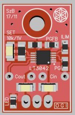
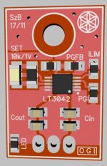
It seems that the connection from thermal pad of the LT3042 to the GND plane is made by only two vias which I find insufficient for effective heat dissipation. I also do not see a need for two bulky film capacitors. I would use only ceramic capacitors on the top side of the board.
Regards,
Oleg
Regards,
Oleg
Hi OlegSh, you have right: I did not refresh the copper pour on the top after setting thermals correctly, but I know that, thanks!
It is not neccessary to build-in the film caps, but I want to have this option anyway.
LT3042 datasheet writes:
"Voltage and temperature coefficients are not the only sources of problems. Some ceramic capacitors have a piezoelectric response. A piezoelectric device generates voltage across its terminals due to mechanical stress upon it, similar to how a piezoelectric microphone works. For a ceramic capacitor, this stress can be induced by mechanical vibrations within the system or due to thermal transients."
Cheers!
You can minimize this by choosing relatively small capacitances (e.g., max 1μF), choosing relatively small packages (e.g., 0603 or 0805 instead of 1206) and buying ceramic caps that have been optimized for low acoustic noise, such as the GJ8 series from Murata.LT3042 datasheet writes:
"Voltage and temperature coefficients are not the only sources of problems. Some ceramic capacitors have a piezoelectric response. A piezoelectric device generates voltage across its terminals due to mechanical stress upon it, similar to how a piezoelectric microphone works. For a ceramic capacitor, this stress can be induced by mechanical vibrations within the system or due to thermal transients."
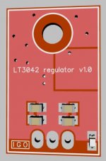
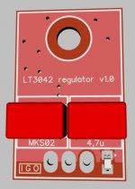
Looks better but still only two vias for heat transfer away from the reg? You can skip the caps on the back side of the PCB entirely and squeeze three 0805 2u2 caps for input and output on the top side. You can also move the LED to the top side too. Is there special reason to have a cut out rectangle in the GND on the bottom side?
You can minimize this by choosing relatively small capacitances (e.g., max 1μF), choosing relatively small packages (e.g., 0603 or 0805 instead of 1206) and buying ceramic caps that have been optimized for low acoustic noise, such as the GJ8 series from Murata.
This shouldn't be a problem in this case. Those low acoustic noise type is for HF switching power supply as they tend to buzz in audio frequency. I do care about two things on LT3042. The first would be the support of fast-start up feature. (Need PGFB, and no I-limit resistor) Second, a larger space for R-set. The noise performance is solely depends on this resistor. Susumu RG or Vishay s102k is preferred for low 1/f performance.
I've seen it with some LDO linear regulators as well, for example, with the LT3083. The datasheet surely mentions it for a reason?This shouldn't be a problem in this case. Those low acoustic noise type is for HF switching power supply as they tend to buzz in audio frequency.
- Home
- Amplifiers
- Power Supplies
- Yet another ultra low noise high PSRR LDO - LT3042