Hi
I am a complete beginner, I have bought the Chinese 5Z3P 6N9P EL34 kit
from E-Bay. Reading some of the threads about this kit, it looks as though
I should build it from Ezequiels circuit. I am confident in the building of it but I am having a problem with the power supply suggested by Ezequiel.
If I use the same power transformer that came in the kit, can I parallel the
High voltage windings and use it on the solid state rectifier circuit? Or can I just use the original 5Z3P power supply with Ezequiels modded amplifier?
I'm not sure that it is safe practice to parallel a centre tapped high voltage
winding. I would like to use Ezequiels circuit as I have a couple of 6SN7's
in my spares kit. I would greatly appreciate any help.
Hi
I am a complete beginner, I have bought the Chinese 5Z3P 6N9P EL34 kit
from E-Bay. Reading some of the threads about this kit, it looks as though
I should build it from Ezequiels circuit. I am confident in the building of it but I am having a problem with the power supply suggested by Ezequiel.
If I use the same power transformer that came in the kit, can I parallel the
High voltage windings and use it on the solid state rectifier circuit? Or can I just use the original 5Z3P power supply with Ezequiels modded amplifier?
I'm not sure that it is safe practice to parallel a centre tapped high voltage
winding. I would like to use Ezequiels circuit as I have a couple of 6SN7's
in my spares kit. I would greatly appreciate any help.
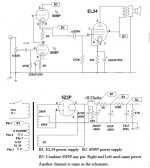
OK, after reading through the plethora of information on this site (thank
you everyone) I think I know how to proceed. I will go with the diodes rather than the 5Z3P. I'll use 2 BYT12 fast recovery diodes (1000v) on each end of the centre tapped HV winding, with the cathodes joined at the reservoir capacitor/ choke input. using the centre tap as 0V.
Grogger-
It would be helpful if you could post the schematics you are referring to - I think the Chinese eBay amp schematics (and perhaps the components?) do change from time to time.
I don't know exactly what you mean by 'paralleling the secondaries' on the power transformer.
For my build, I was only concerned with getting the right B+ voltages to supply the Ezequiel circuit, and I managed to do that with the tube rectifier circuit and supplied transformer. You may need to do some 'adjusting' with the resistors in the power supply once you get the amp wired up and running with all the tubes; IIRC I may have done this on my build.
I wouldn't jump to diode rectification without a good reason, since the chassis already has the hole for the tube rectifier, I think.
Attachments
Hi
Thank you for your reply.
I originally thought that if I used a bridge rect, I would only need one HT winding, which made me think I might have to parallel the centre tapped winding to achieve one winding.
After reading some info from this site, I realised I had it totally wrong. I
have now got a circuit together which I think is correct (or close).

I've tried to attach an image of the circuit
but I don't know if it's worked.
The reason I've gone for diode rectification is that I want to build in a tone
control circuit using two ECF82 valves. putting them on the same chassis as the amplifier brings them pretty close to the area where the valve
rectifier would be. I read somewhere that small signal valves in such close approximation to the rectifier valve would cause hum. The tone control
circuit is a tried and tested design by M Holmes and J Moseley for the Maplin Newton Preamp. So I should be able to build this part OK.
The heater current for these valves would come from the 5v ac winding
which is spare, not using the 5Z3P. Rectified using a Schottky bridge
and fed to a large electrolytic cap to bring the voltage to around 6V dc.
I'm starting off not having a clue, but trying to learn as I go.
Regards
Thank you for your reply.
I originally thought that if I used a bridge rect, I would only need one HT winding, which made me think I might have to parallel the centre tapped winding to achieve one winding.
After reading some info from this site, I realised I had it totally wrong. I
have now got a circuit together which I think is correct (or close).
I've tried to attach an image of the circuit
but I don't know if it's worked.
The reason I've gone for diode rectification is that I want to build in a tone
control circuit using two ECF82 valves. putting them on the same chassis as the amplifier brings them pretty close to the area where the valve
rectifier would be. I read somewhere that small signal valves in such close approximation to the rectifier valve would cause hum. The tone control
circuit is a tried and tested design by M Holmes and J Moseley for the Maplin Newton Preamp. So I should be able to build this part OK.
The heater current for these valves would come from the 5v ac winding
which is spare, not using the 5Z3P. Rectified using a Schottky bridge
and fed to a large electrolytic cap to bring the voltage to around 6V dc.
I'm starting off not having a clue, but trying to learn as I go.
Regards
The reason I've gone for diode rectification is that I want to build in a tone
control circuit using two ECF82 valves. putting them on the same chassis as the amplifier brings them pretty close to the area where the valve
rectifier would be. I read somewhere that small signal valves in such close approximation to the rectifier valve would cause hum.
There's probably room at the front of the chassis for two 9-pin tubes, but it will get a bit cramped with 4 pots (3 of them ganged) across the front.
Still, probably possible.
Are you using the PSU PCB (the kits come with one now?) or wiring on lug strips? AFAIK, it's not just the rectifier tube that can be a hum source, but the AC wiring to that tube. So you'll want to get all the AC away from your preamp area as much as possible, I think.
Are you going to build a cover/cage over the amp? That rectifier tube hole won't be a problem? (I suppose you could put in the tube and light it up with an LED like those cheap 'tube amps' on eBay....
 )
)Other possibilities you've probably considered: Building the amp as a power amp only and building a separate preamp on its own chassis or using a different (larger) chassis for the 'integrated' amp you've planned, running the extra tube heaters from the same winding as the other tubes (or adding a separate filament transformer under the chassis if necessary?), etc..
You may have a better workshop than me, but I put drilling holes in stainless well down on my list of 'favourite jobs'....so a nice homebuilt (larger) chassis with an aluminum top plate would be a route I'd consider.
The first tube guitar amp I built from scratch (on a recycled chassis) had extra gain stages, lotsa tone controls, effects loop, etc.. I never did get it working properly, and I put my 'build the ultimate amplifier' project idea aside for a later time. Next attempt was something a lot simpler and it worked 'perfectly', and was more satisfying.
Have you figured out the B+ you expect to get from your diode rectifier supply?
Neat project, BTW....keep those pictures coming!
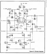
Is this your tone control circuit (attached) ?
Attachments
I've tried to attach an image of the circuit
but I don't know if it's worked.
Displays properly for me; thanks.
I just had a quick look at your schematic.
I'm sure you won't wire it that way, but you have a short across the EL34 heater wiring in the drawing, which you can correct easily at this stage with an eraser. (No melted wire insulation and humming transformer...)
Do you think a fuse is necessary in the B+ supply?
My question about B+ is answered; it looks like you have used PSU Designer or similar to figure out your new B+ voltage?
Hi
First of all, many thanks for pointing out the error on my schematic drawing. I hadn't noticed and would probably have wired it that way.
You've saved me some embarrassment, stress and a fire extinguisher refill!
I'll wire the PSU using lug strips in the area where the valve base for the 5Z3P would have been. Then put a small aluminium plate on the top of the chassis to cover the unwanted hole. I'm going to spray the chassis black anyway.
I should be OK with the drilling of the chassis, I have some diamond tipped hole cutters. I included the fuse in my drawing just because I thought it might be good practice. I had a KT88 valve go faulty in my Icon Audio amp, that took the chassis mounted fuse out. Don't know how much more damage would have been done if it wasn't there.
The tone control circuit is indeed the one you've indicated, I built it years ago as a Maplin kit and it worked for me, I wish I hadn't sold it. I'm not sure whether it's OK to talk about tone controls in the valve world. I've
read that many people frown on tone controls as unnecessary. My hearing isn't great, forty years in front of large speakers playing guitar in bands has done some damage, so some boosting or cutting at some frequencies make some recordings sound better.
Anyway, I am very grateful for your help and advice and to others for their postings which have pointed me in the right direction.
Regards
Terry (Grogger)
Terrry-Anyway, I am very grateful for your help and advice and to others for their postings which have pointed me in the right direction.
You are most welcome; that's why we are here. I get lots of help with my 'beginner questions' from folks here. When there is a topic where I actually have some knowledge/experience, it's a good chance for me to 'pay back' a bit.
Of course, we demand construction pictures as payment! Modified Chinese valve amp kit
Hi
Finished earlier than I thought. Sounds excellent, no hum or buzz.
I don' know whether my B+'s are correct but the amp doesn't seem to run too hot, all seems OK.
Thanks go out to :-
Mr E Duttman and Ezequiel (Better Chinese amp)
M Holmes and J Mosely ( Maplin Millenium tone circuit)
Victoria Guy (Many thanks for your guidance)
All of the guys whose posts and info on this site have helped me find my way)
Photo's attached.
Attachments
-
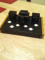 photo 4.JPG81.1 KB · Views: 78
 -
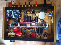 photo 4(4).JPG144.3 KB · Views: 78
 -
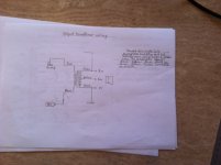 photo 3(6).JPG96.1 KB · Views: 76
 -
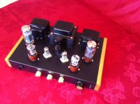 photo 2(7).JPG123.9 KB · Views: 77
 -
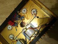 photo 2(1).JPG141.7 KB · Views: 125
 -
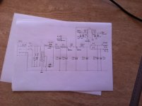 photo 2(6).JPG101 KB · Views: 129
 -
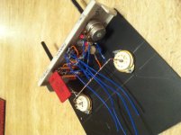 photo 1.JPG124.6 KB · Views: 116
 -
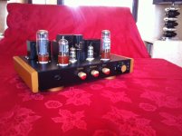 photo 1(6).JPG112.9 KB · Views: 131
 -
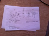 photo 1(5).JPG109.1 KB · Views: 132
 -
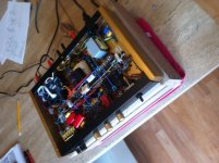 photo 5(3).JPG138.7 KB · Views: 71
- Status
- This old topic is closed. If you want to reopen this topic, contact a moderator using the "Report Post" button.
- Home
- Amplifiers
- Power Supplies
- 5Z3P 6N9P EL34 Chinese amp kit