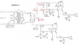
I'm working on this little Mondial preamp and I'm playing around with upgrading the power supply section. I'm looking for suggestions. I included a modified image of the basic power supply layout. Its just a basic emitter follower with an RC filter between the pass transistor and line stage. I left the negative rail unmodified in this drawing so you can see what it looks like unchanged. The red items are those I have already changed or plan to change. The CRC filter consisting of C1/R1/C2 has already been installed and it works great, dropping the measured ripple from 22mv rms before the upgrade to < 1mv rms after. I plan to install some small electrolytics across the Zener's. I also installed a larger 10VA transformer replacing the 5VA unit that's why those letters are red.
What I'd like to do is improve the noise performance enough that I can do away with R4 to minimize the output impedance of the regulator. I'm assuming that this is there to minimize any residual mains noise and zener noise that comes through the regulator. The TIP31C/32C transistors have fairly low gain. I know that increasing the gain here would help, but I want to stick with the TO-220 style case. I was looking at TO-220 darlingtons, but they don't seem to have great performance at this low of a current level (10 ma). I was just thinking about installing the 2SC4793/2SA1837 to replace them. Those offer about 3X the gain over the TIP parts and are really cheap, any ideas for replacements here? Or any comments on any other parts of the regulator circuit to clean it up?
What I'd like to do is improve the noise performance enough that I can do away with R4 to minimize the output impedance of the regulator. I'm assuming that this is there to minimize any residual mains noise and zener noise that comes through the regulator. The TIP31C/32C transistors have fairly low gain. I know that increasing the gain here would help, but I want to stick with the TO-220 style case. I was looking at TO-220 darlingtons, but they don't seem to have great performance at this low of a current level (10 ma). I was just thinking about installing the 2SC4793/2SA1837 to replace them. Those offer about 3X the gain over the TIP parts and are really cheap, any ideas for replacements here? Or any comments on any other parts of the regulator circuit to clean it up?
Attachments
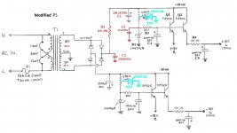
Maybe you could use two stages of regulation between the raw and ripply 28V supply, and the base of the emitter follower. This would improve "line regulation", i.e., the change in Vout which is caused by a 1V change in Vin. Here's a schematic.
It subdivides the 470 ohm resistors into two series pieces, and regulates those intermediate nodes to +/- 22V.
_
It subdivides the 470 ohm resistors into two series pieces, and regulates those intermediate nodes to +/- 22V.
_
Attachments
Okay, that's an idea, it would put a decent additional load on the PS though. I had seen where some had used a current limiting diode in place of R2 to help tame some of the ripple. But I'd likely need a CLD of 18ma or more to feed the 4746A with enough current to stay safely way from the zener knee.
- Status
- This old topic is closed. If you want to reopen this topic, contact a moderator using the "Report Post" button.