I've been building a rackmount power supply for some onboard guitar electronics. The power is supplied via a 13 pin cord, where pin 12 is V+ and pin 13 is V-. The electronics can work via bipolar PSU or unipolar. I built unipolar.
After some help from the forum, I got the unit up and running using a simple 110V-to-24V AC adaptor, and then a stepdown AC-DC regulator to provide 9 V unipolar power.
The only problem I'm getting 8 dB higher noise floor when I use the standard 3 prong IEC jacks I intended it to use. This higher noise floor is audible as 60 hz hum when brought up to clearly audible levels. When I plug my 3 prong IEC cord into a 2 prong ground lift "cheater" adaptor, this hum disappears, the noise floor drops 8 dB, and performance is equivalent or 1-2 dB better than the noise floor running off a 9V battery.
So I guess I have a ground loop? I understand using these 2 prong cheaters is considered unsafe. Is this true? Because if it's not unsafe, that would be the easiest solution - just keep using the cheater plug. It seems to be working fine. I also in addition to the regular 2 prong cheater have an old Ebtech "Hum X" line filter which when used in place of the 2 prong cheater seems to accomplish about the same job.
Still it would be nice to fix the problem properly. Any suggestions to start?
Last edited:
Some questions:
Is this power supply for a single unit or multiple units? Are you floating the low voltage side of the power supply, or are you grounding the low voltage AC or DC anywhere?
If it's just a single device and you are grounding the low voltage side somewhere in your power supply, the solution is as simple as ungrounding it. It gets more complicated if that's not the case.
It's for a single electronics unit onboard the guitar. I'll try to explain the wiring/grounding scheme as best as possible. I can post a picture if this doesn't make sense.
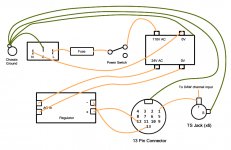
IEC wiring
IEC Live --> power SPST switch --> transformer 110V connection --> Regulator input
IEC Neutral --> transformer 0V connection --> Regulator input
IEC Ground --> soldered to chassis and shields of 1/4" output audio jacks coming out of chassis unit
Regulator wiring
Regulator + output --> pin 12 of 13 pin cable (to supply + voltage to guitar onboard electronics)
Regulator - output --> pin 13 of 13 pin cable (in bipolar supplies, this pin provides - voltage)
Rest of guitar wiring
The rest of my guitar electronics/humbuckers/shielding etc. is grounded via the shield of the standard 1/4" output of my guitar.
Last edited:
Even more unclear.
The 120VAC connection is to transformer primaries, the transformer secondaries are connected to this "regulator", and the regulator outputs, via this mysterious "13 pin cable", are connected to one or more 1/4" jacks to feed 9VDC to the guitar, is this correct?
Are the 1/4" jacks the only place after the transformer secondaries that the circuit is connected to the chassis ground? Are the jacks being grounded by both a metal-to-metal chassis connection as well as a soldered wire to the ring lug? Is the "V-" of the regulator also connected to the ring lug of the jack?
What is this regulator? Is it capable of +9VDC and -9VDC simultaneous supply, but you are trying to wire it for +9VDC only? One pin is described as "V+", another as "V-", is another described as ground in the documentation?
Does the guitar have two 1/4" jacks, one for 9VDC supply, and the other for output? This onboard device you have is being grounded at both of these 1/4" jacks?
Last edited:
Since you will be "holding" your Guitar, it is especially important that all the Safety Earth connections are properly implemented.
The Mains MUST be ISOLATED from your electronics.
Is your 115:24Vac transformer an "isolating" transformer?
You said
The Mains MUST be ISOLATED from your electronics.
Is your 115:24Vac transformer an "isolating" transformer?
You said
Is your Mains PE wire solidly and mechanically and permanently secured to your Chassis?soldered to chassis
Okay, guys. Sorry if I was unclear or mixed anything up. As you can probably tell, I'm learning as I go.
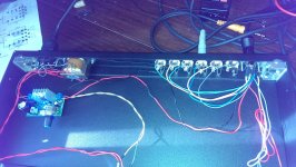
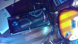
I've attached pictures of the chassis. They're discolored because my phone camera is broken, not because I'm using instagram filters.")
The regulator it appears is bipolar. I am using this one:
NEW LM317 Voltage Regulator AC DC IN 3 40V OUT DC1 25V 37V Power Supply Board | eBay
I trimmed it by putting my multimeter probes across the + and - terminals of the output and adjusting the trimmer until I got the total desired voltage differential (9V currently).
I didn't notice this before, but when I measure the + output relative to chassis ground, I am getting 4.9V. When I measure the - output relative to chassis ground, I am getting -3.9V. So they seem to be asymmetric. Is this normal behavior? I would expect both if it's bipolar to be equal and opposite. Also, 3.9V + 4.9V = 8.8V, but when I measure directly across the terminals, it reads 9V. What does this 200 mV differential represent?
The transformer I'm using is ultra cheap and was my initial suspicion for the problem. If it is the issue I will order a Hammond one from mouser to replace it with my next order. This is what I'm using:
1pc AC Power Transformer Input AC220 110V 60Hz Output AC6 12 24V 120mA 3VA | eBay
I believe it is an isolating transformer. When I measure continuity across the 0V to 0V leads, or 110V to 24 V leads I get nothing, so I don't think it's conducting exactly, but I'm not sure how to be precisely sure of this.
To elaborate on how this is all working together, the guitar has two cables connected to it. One is a standard 1/4", which carries the output from the humbucking pickups and grounds the bridge/shielding/humbuckers.
The other cable is the 13 pin cable. Pins 1-6 of this carry out from the guitar the audio signal from the 6 piezo saddle bridge pickups. Pins 12 and 13 supply phantom power to an onboard hexaphonic (six channel) preamp for the 6 bridge saddle pickups. I am using a Ghost system at the moment:
As you can see from the chassis, what I've done is break out the 13 pins so that pins 1-6 go to TS output jacks, so I can record each piezo pickup independently. Pins 12 and 13 connect to the regulator to supply power to the onboard piezo preamp.
As far as I can tell, the regulator board has no direct connection to ground. Its inputs are sourced by Neutral and Live from the IEC. Its outputs go to the pins 12 and 13 which feed the onboard guitar six channel preamp.
My IEC earth is soldered to a ground lug which is bolted down at the base of the transformer and contacting the raw chassis metal. The earth IEC terminal has good conduction/continuity when tested with raw metal of all components of the chassis, as well as the shields of the 6 piezo chassis TS output jacks.
Thanks for any further feedback. If I'm still not making sense, I can draw diagrams.
I've attached pictures of the chassis. They're discolored because my phone camera is broken, not because I'm using instagram filters.
The regulator it appears is bipolar. I am using this one:
NEW LM317 Voltage Regulator AC DC IN 3 40V OUT DC1 25V 37V Power Supply Board | eBay
I trimmed it by putting my multimeter probes across the + and - terminals of the output and adjusting the trimmer until I got the total desired voltage differential (9V currently).
I didn't notice this before, but when I measure the + output relative to chassis ground, I am getting 4.9V. When I measure the - output relative to chassis ground, I am getting -3.9V. So they seem to be asymmetric. Is this normal behavior? I would expect both if it's bipolar to be equal and opposite. Also, 3.9V + 4.9V = 8.8V, but when I measure directly across the terminals, it reads 9V. What does this 200 mV differential represent?
The transformer I'm using is ultra cheap and was my initial suspicion for the problem. If it is the issue I will order a Hammond one from mouser to replace it with my next order. This is what I'm using:
1pc AC Power Transformer Input AC220 110V 60Hz Output AC6 12 24V 120mA 3VA | eBay
I believe it is an isolating transformer. When I measure continuity across the 0V to 0V leads, or 110V to 24 V leads I get nothing, so I don't think it's conducting exactly, but I'm not sure how to be precisely sure of this.
To elaborate on how this is all working together, the guitar has two cables connected to it. One is a standard 1/4", which carries the output from the humbucking pickups and grounds the bridge/shielding/humbuckers.
The other cable is the 13 pin cable. Pins 1-6 of this carry out from the guitar the audio signal from the 6 piezo saddle bridge pickups. Pins 12 and 13 supply phantom power to an onboard hexaphonic (six channel) preamp for the 6 bridge saddle pickups. I am using a Ghost system at the moment:
An externally hosted image should be here but it was not working when we last tested it.
As you can see from the chassis, what I've done is break out the 13 pins so that pins 1-6 go to TS output jacks, so I can record each piezo pickup independently. Pins 12 and 13 connect to the regulator to supply power to the onboard piezo preamp.
As far as I can tell, the regulator board has no direct connection to ground. Its inputs are sourced by Neutral and Live from the IEC. Its outputs go to the pins 12 and 13 which feed the onboard guitar six channel preamp.
My IEC earth is soldered to a ground lug which is bolted down at the base of the transformer and contacting the raw chassis metal. The earth IEC terminal has good conduction/continuity when tested with raw metal of all components of the chassis, as well as the shields of the 6 piezo chassis TS output jacks.
Thanks for any further feedback. If I'm still not making sense, I can draw diagrams.
Attachments
Last edited:
As far as I can tell, the regulator board has no direct connection to ground. Its inputs are sourced by Neutral and Live from the IEC. Its outputs go to the pins 12 and 13 which feed the onboard guitar six channel preamp.
You seem to be confusing yourself. I doubt this is true; if it were you wouldn't need the transformer and the board would have blown up long ago.
I think a diagram of what you did and what wires you connected is necessary. You need to put some effort into documenting exactly what you did and not just wing it like you did above.
Well, your wiring is conducive to ground loops, but I don't think that's your big problem.
Where did you get the idea to wire the unipolar supply to the bipolar supply pins? Was that in any kind of literature provided to you or from a tech support source for your product?
I looked on the online literature for a Hexpander and it mentions that it can draw the power from the 13pin MIDI instead of a 9V battery.
Since 9V batteries are obviously unipolar, the Hexpander probably has a bias circuit for onboard electronics, and it's very possible that that bias circuit is used for both 9V and MIDI supply; in other words the Hexpander could be designed to only use the +V on pin 12 and the shield ground. If this was the case you would actually not wire the regulator "-" to pin 13 but to the 13 pin connector shield.
In any case the way you have it wired won't cut it, the standard 13 pin MIDI pinout is for bipolar supplies, and your regulator isn't bipolar.
And after you sort this out, you can start to worry about ground loop. I would start by removing the separate grounding wires for the 1/4" and 13 pin connector and make sure they have a good solid no-resistance connection to the chassis.
Thanks leadbelly. I can definitely grind some of the powdercoat off on the panel and let the 1/4" and 13 pin connect to chasis that way if you think it will help my ground loop problem.
Regarding the Hexpander onboard preamp, it can function with unipolar or bipolar power supply. I have talked to the guys who make it and they have confirmed this. I have also proven it can function just fine with a single unipolar power supply (by using a unipolar 9V battery connected to pins 12/13). The standard "13 pin spec" for this format, designed by Roland, however, is bipolar with pin 12 to have 7 V+ and pin 13 to have 7 V-. So technically that's what it's designed for. But it definitely works either way, unipolar or bipolar.
I would actually prefer to supply a unipolar current to the guitar via pin 12 though. I already have the parts for this. Also, this way I can most easily use it to simultaneously power other onboard guitar electronics that usually operate off a 9V battery and get rid of all batteries.
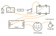
Are you suggesting I could try rewiring it like attached for unipolar supply? I could maybe just leave pin 13 unwired to anything? Or would I wire pin 13 to chassis also?
Thanks again.
Regarding the Hexpander onboard preamp, it can function with unipolar or bipolar power supply. I have talked to the guys who make it and they have confirmed this. I have also proven it can function just fine with a single unipolar power supply (by using a unipolar 9V battery connected to pins 12/13). The standard "13 pin spec" for this format, designed by Roland, however, is bipolar with pin 12 to have 7 V+ and pin 13 to have 7 V-. So technically that's what it's designed for. But it definitely works either way, unipolar or bipolar.
I would actually prefer to supply a unipolar current to the guitar via pin 12 though. I already have the parts for this. Also, this way I can most easily use it to simultaneously power other onboard guitar electronics that usually operate off a 9V battery and get rid of all batteries.
Are you suggesting I could try rewiring it like attached for unipolar supply? I could maybe just leave pin 13 unwired to anything? Or would I wire pin 13 to chassis also?
Thanks again.
Attachments
Last edited:
I would think that bonding the neg dc output of the regulator to ground would set the reference voltage to 0vdc thereby giving you the +9vdc that the hexpander is looking for. The literature that I read said nothing about bipolar or unipolar supplies (or phantom power, for that matter) but only indicated a battery terminal on the board and a power output for driving additional electronics, inside the guitar. So it stands to reason that it is looking for 0vdc and +9vdc, not bipolar voltages. Not sure why you're using a variable regulator, either, instead of something based on a, say, a 7809 regulator with a rectifier and a filter cap or two.
Also, can I ask why you're using the 24vac tap on that transformer instead of the 12vac tap? It seems to me that you'd make life easier on the voltage regulator by providing it with an input that is closer to its output so that it doesn't have to drop so much extra voltage.
Thanks W0J0. That makes sense. I just didn't know how to hook it all up. There wasn't any particular reason I did it that way. I'll send the negative output from the regulator to ground when I get home tonight.
Also, the regulator I used was $10 on ebay preassembled. It was simple and easy. The variability was favorable to me, as the electronics can go up to 18V unipolar supply. I figure I will go up to 14V or so. That's why I used the 24V transformer output. More flexibility for voltage in the end.
The 13 pin standard format again is built to have pin 12 as 7 V+ and 13 as 7 V- (bipolar), so that is what the hexpander works off of when connected to standard Roland 13 pin gear like the Roland GK20. But as stated, again, unipolar via pin 12 is reportedly fine as well.
Last edited:
- Status
- This old topic is closed. If you want to reopen this topic, contact a moderator using the "Report Post" button.
- Home
- Amplifiers
- Power Supplies
- Noise floor 8 dB higher on 3 prong vs 2 prong "cheater" jack?