Hello everyone.
I have a question related to chokes and HV anode power lines.
I read some of Tubelab's posts where he advocates placing the choke in the return line of a PSU to avoid having to deal with the HV of the anode line.
Please help me find an answer to the following queries.
1. The choke must be place in series with the return line? Does this mean from the GND of the anode capacitor to GND itself?
2. How does this affect voltage and current ratings? Am I still bound by the current demand on the anode line? eg if my tube draws 100mA must I still choose a choke capable of such current even if such choke is placed in the GND path of the power supply?
Thank you very much and sorry for the stupid question")
I have a question related to chokes and HV anode power lines.
I read some of Tubelab's posts where he advocates placing the choke in the return line of a PSU to avoid having to deal with the HV of the anode line.
Please help me find an answer to the following queries.
1. The choke must be place in series with the return line? Does this mean from the GND of the anode capacitor to GND itself?
2. How does this affect voltage and current ratings? Am I still bound by the current demand on the anode line? eg if my tube draws 100mA must I still choose a choke capable of such current even if such choke is placed in the GND path of the power supply?
Thank you very much and sorry for the stupid question
All the current flows through C1 so it may fail as well. Probably not an issue though if the choke is decently sized and you don't have squirrels or mice chewing at the insulation!
FWIW, the ARRL (in their handbook) had no problem filtering the return to center tap, but recommended 2 chokes in series. This reduced the effect of parasitic capacitance in the trannie, but was mostly relevant for low voltage applications.
Horowitz and Hill also suggested that regulating the return line was a good idea.
Thank you Jackinnj. That is very valuable information!
I have an odd situation. A SE based on the large GM100 tubes.
I am running deep A2 (positive voltage on grid) to bias the tubes up to 280mA @1500v (and no...1500v on the anode alone are unable to solicit that much current without positive bias). So I have a main B+ line of 1500v through a SE transformer feeding a GM100 tube.
My current supply is:
CRC + C (and L in return path)
Bridge filament (1260v) - IXYS HV bridge - 5uf 2500v PIO - 100ohm 50w resistor - 550uf caps
After that each Gm100 has its own array of MKP capacitors for a total of 25uf each.
I was hoping to avoid dumping large pulsating surges of current back into the common ground and thought that maybe a choke on the return line could be a good idea. the transformers are connected (negative secondary) to the common GND so hum and buzz is a concern.
I chose a hammond 750mA 0.6H to place on the return path from the 550uf capacitor bank. Should work nicely without too much stress.
What happens if the choke fails?
depends on how it fails...if it burned out, then the dc resistance is close to zero, if it failed as an open ckt, then any leak to ground will be a sakety hazard, dangerous...
Df96 i jave built a gu46 amp; an ab2 gu81m pp amp and now i am finishing up the gm100 amp.

Gor example to avoid corona discharge or hv problems i have built the entire psu unit on plexiglass and made a cover. Every cap has its bleeder and balancer resistor.
There are 220v fuses and microwave fuses on the hv ac lines.
The entire chassis is hardwired to gnd of the ac outlet.
Gor example to avoid corona discharge or hv problems i have built the entire psu unit on plexiglass and made a cover. Every cap has its bleeder and balancer resistor.
There are 220v fuses and microwave fuses on the hv ac lines.
The entire chassis is hardwired to gnd of the ac outlet.
Can I suggest you post a schematic of what you are proposing, and then comments can refer to that - it will avoid ambiguity and misconceptions. The schematic should extend to your load circuits, as they will include protection items as well as identify fault paths to consider.
Given the extra hazards with your setup, it would be wise to throw as much protection in as possible, and to work through all plausible failure modes to appreciate what may happen.
You are using ss rectifier, which simplifies the discussion. Each part really needs to be described in enough detail too - eg. the transformer details and ratings should be included, including DCRs, and if possible the characterised snubber (eg. using the Quasimodo type technique). A PSUD2 response will also help.
With respect to the simple circuit shown by AJT, an open-circuited choke would not per se cause additional fault parts or an external hazard. One would assume that caps on either side of the choke have bleeds, and so B+ would drain to zero, and the first cap would have -B+ on it. The choke winding would have -B+ on it (depending on where the open-circuit occurred), so the choke may further break-down, depending on whether you were cutting corners with the choke for starters - which you shouldn't because PSUD2 will alert you to peak winding voltage during start-up conditions, which may force you to use a HV choke anyway.
Last edited:
I am completing the schematic but the interlock is not necessary per se. The amp currently weighs 55kg and cannot be flipped and/or manipulated. The cover has 2x 1942SEA hammonds on it making it exceedingly heavy to even tilt.
The main HV cap bank is enclosed in lexan so electrical arcing to chassis is impossible and so are dangerous explosions. the main HV is fuse protected using a 750mA microwave fuse.
The 220v are fuse protected and softstarted as well. The amp has thermal shutdown capability sensing heat on the capacitor bank and the internal heatsink of the driver board.
the solder points have been smoothed polished to avoid corona discharge. All caps have bleeders and, when used in series, 5w 560k balancing resistors. The bridge is a 1800v unit from IXYS.
Once the HV is removed the filaments stay on for 5 seconds more to drain the caps. The bleeders take care of the rest.
The transformers is a 1000VA 0.8A 1260v-0v toroidal unit. DCR was once measured but I lost the data.
The secondary voltages (driver voltages) are supplied by a smaller transformer. No chance for one to arc to the other.
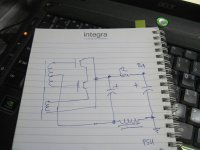
Sorry I tried my best with bitmap which is attached. It is all I can do from work.
The main HV cap bank is enclosed in lexan so electrical arcing to chassis is impossible and so are dangerous explosions. the main HV is fuse protected using a 750mA microwave fuse.
The 220v are fuse protected and softstarted as well. The amp has thermal shutdown capability sensing heat on the capacitor bank and the internal heatsink of the driver board.
the solder points have been smoothed polished to avoid corona discharge. All caps have bleeders and, when used in series, 5w 560k balancing resistors. The bridge is a 1800v unit from IXYS.
Once the HV is removed the filaments stay on for 5 seconds more to drain the caps. The bleeders take care of the rest.
The transformers is a 1000VA 0.8A 1260v-0v toroidal unit. DCR was once measured but I lost the data.
The secondary voltages (driver voltages) are supplied by a smaller transformer. No chance for one to arc to the other.
Sorry I tried my best with bitmap which is attached. It is all I can do from work.
Attachments
The aim is to make 0V at the other end of the choke.
A 280mA load on that circuit will likely only give 1270V with 6Vpp ripple.
Blowing the secondary HT winding fuse may stress the transformer secondary due to leakage inductance. A tuned snubber across the winding would alleviate that, and perhaps minimise some rectifier noise.
A 280mA load on that circuit will likely only give 1270V with 6Vpp ripple.
Blowing the secondary HT winding fuse may stress the transformer secondary due to leakage inductance. A tuned snubber across the winding would alleviate that, and perhaps minimise some rectifier noise.
- Status
- This old topic is closed. If you want to reopen this topic, contact a moderator using the "Report Post" button.
- Home
- Amplifiers
- Power Supplies
- Chokes in the return line - bypassing the HV problem?