I'm building a +24V and +48V PSU to power up a mic pre. The schemo is below. However, I built it in 2 section: 24V and 48 V sections and just connected the 2 as per the schematic from transformer to the second bridge at the LM317. The problem is that I'm only getting +34V at the 317 output. How should I wire the trimpot (pin 1,2,3)? It's like there is no doubling. Transformer is 24VAC. The 7824 reads +24V at the output. Any thoughts? Thanks
L
L
Attachments
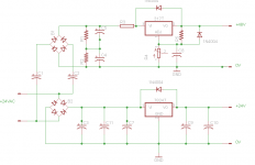
I'm building a +24V and +48V PSU to power up a mic pre. However, I built it in 2 section: 24V and 48 V sections and just connected
the 2 as per the schematic from transformer to the second bridge at the LM317. The problem is that I'm only getting +34V at the 317 output.
This won't work because of the common grounds. Instead, you can have the 24V regulator run off the output of the 48V regulator.
Or, the 24V regulator can run off the same input DC voltage as the 48V regulator, if you don't need much current at 24V,
or want to minimize the current through the 48V regulator.
Last edited:
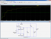
you only need 2 diodes and 2 caps to implement a full wave doubler...
you can still get regulated 48 and 24 volts supplies out of this if that is what you need...
you will need a secondary higher than 24 volts, 27 to 30 volts is better...
regulated 48 volts can be derived from the top cap C1,
regulated 24 volts from the bottom cap, positive of C2...
An externally hosted image should be here but it was not working when we last tested it.
you can still get regulated 48 and 24 volts supplies out of this if that is what you need...
you will need a secondary higher than 24 volts, 27 to 30 volts is better...
regulated 48 volts can be derived from the top cap C1,
regulated 24 volts from the bottom cap, positive of C2...
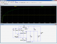
voltage doublers quickly lose voltage from a peak as it is loaded..
you need a cap rated for at least 1.4 x Vsec,
so that if using a 24 volt sec, cap is charged to about 34 volts,
so you can use 50 volt rated caps..
but if you have those 63 volts cap already, then go ahead and use it...
depending on your load current, i supposed 24 volts ac secondary will work..
and you can use it if you have them on hand already...
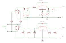
Thanks a lot guys. I spotted a problem which was that the 24V had to be fed to the 48V to get the ~66VAC. How about this circuit? How would I connect the pins of the trimpot?
The circuit then becomes almost like the one I gave in #7, except it is slightly more disadvantageous regarding the efficiency, and the sensitivity to capacitors C1 and C2.
R4 should be associated with a fixed resistor, and its wiper connected to the adj terminal of the 317.
You have to eliminate R3, or place a decoupling cap in front of the 317
Last edited:
- Status
- This old topic is closed. If you want to reopen this topic, contact a moderator using the "Report Post" button.
- Home
- Amplifiers
- Power Supplies
- Voltage Doubler PSU-Newbie