Hi. I am wondering how to install a front power switch to an amp.
Switch/Button
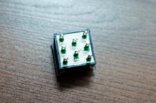
For safety I have read that a DPST type switch is recommended to isolate line and neutral. Switch data sheet: http://www.nkkswitches.com/pdf/cwscilluminated.pdf
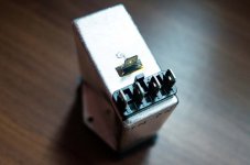
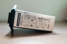
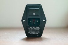
Power entry module
The back power entry unit has a power rocker and dual fuses for switching between 115v and 230v. The back lugs are 1 earth, 2 line, 2 neutral. I'm assuming the twin lines are to connect to twin 115v primaries of a transformer so that they can be switched between 115v and 230v. Data sheet: http://www.farnell.com/datasheets/1511815.pdf
What I'm not clear is how to actually wire the switch between the power entry module and the transformer. And how does one supply the switch LED power from the transformer? I count 7 lugs on the back of the switch.
Switch/Button
For safety I have read that a DPST type switch is recommended to isolate line and neutral. Switch data sheet: http://www.nkkswitches.com/pdf/cwscilluminated.pdf
Power entry module
The back power entry unit has a power rocker and dual fuses for switching between 115v and 230v. The back lugs are 1 earth, 2 line, 2 neutral. I'm assuming the twin lines are to connect to twin 115v primaries of a transformer so that they can be switched between 115v and 230v. Data sheet: http://www.farnell.com/datasheets/1511815.pdf
What I'm not clear is how to actually wire the switch between the power entry module and the transformer. And how does one supply the switch LED power from the transformer? I count 7 lugs on the back of the switch.
The 7 lugs on the back of the voltage conversion switch confirms the complexity of what needs to be inside that specialised switch.
Your front panel switch can directly switch the mains input, or trigger a relay that switches the mains input.
You need to understand how to wire up the converter switch and how to wire up the ON/OFF switch. Don't take chances !
Think this through very carefully.
In the meantime build a Mains Bulb Tester and use it to power up every mains powered project and every modification of a mains powered project.
Only AFTER you have proved that your wiring is correct do you risk powering direct to the mains and then you must use an appropriately rated mains fuse.
Thanks Andrew for the tips, I will definitely be double checking and measuring before supplying any power.
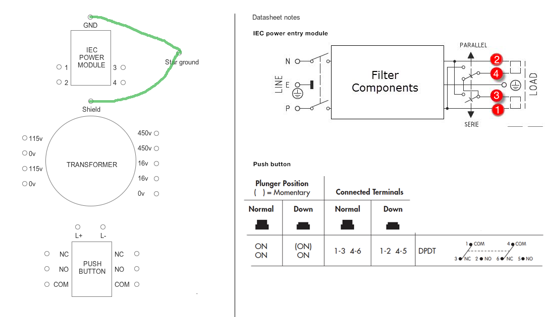
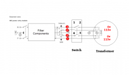
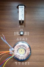
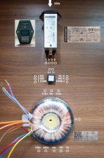
I have drawn out the 3 components I'm trying to wire: Mains input module (115-230v switchable /w built in fuse), transformer (dual 115v primaries for series hookup to 230v), and the DPDT push button.
Can anyone help me with how to wires these three things together?
I have drawn out the 3 components I'm trying to wire: Mains input module (115-230v switchable /w built in fuse), transformer (dual 115v primaries for series hookup to 230v), and the DPDT push button.
Can anyone help me with how to wires these three things together?
Last edited:
use a fuse in the primary circuit of the transformer. The mains input module may satisfy this requirement.
The two 115Vac primary windings of the transformer need to be wired in parallel to be fed from the 115Vac mains supply.
BUT!!!, you can wire then in phase, or out of phase.
Wiring these two primaries incorrectly will destroy your transformer if that fuse does not blow. This is where the Mains Bulb Tester comes to your aid.
It prevents damage to your fuse and to your transformer even if you wire it incorrectly.
All that happens is you see the bulb lit brightly. You now reverse wire ONE primary winding. Test again. If the bulb is out and you have ~114Vac across the transformer windings then you know you have now wired the transformer correctly.
Gradually add on the next stages of the PSU and amplifier testing via that mains bulb tester. It saves you damaging in the event of getting any wiring wrong.
Finally:
do you understand the difference between parallel and series? Do you know which is which?

The nice part of that pic, is that the mains switch can be on the back panel.Is this what you are looking for?
The ON/OFF relay can be triggered with a low voltage switch on the front panel, or even remotely with a trigger signal from another component.
Thanks guys, really appreciate it as I'm struggling with the datasheets and trying to find videos/articles online to explain this.
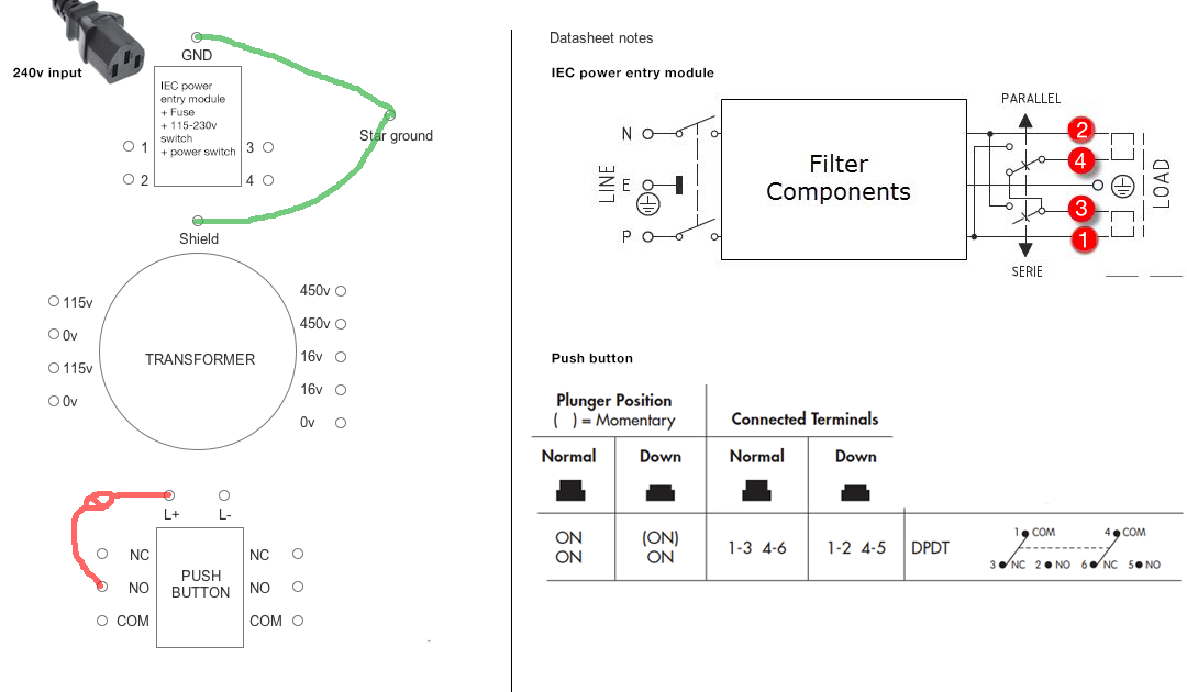
I've updated the diagram /w a bit more detail. As Mark noted, the setup is indeed a power module at the back, with a second mains switch at the front with its LED powered from the PSU (using an appropriate resistor to get the voltage down).
Some context:
- My mains is 230v
- The power module is 115-230v switchable. It doesn't change the voltage, but I believe if wired correctly to the transformer (with 115v dual primaries), it essentially switches from parallel (115v) to series (115v+115v) from the back
- I plan to leave the power module switched ON on the back, and then use the front push button to switch the amp ON and OFF
My issue is that I don't know how to connect the wires. I extracted the relevant sections from the datasheets, but unfortunately it's too advanced for me to read.
For example:
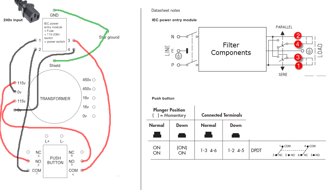
- I'm not confident I know which power entry lugs (labeled 1, 2, 3, 4) is Power-Neutral, Power-Neutral
- Are all four lugs (1, 2, 3, 4) connected to the transformer, or is some other arrangement required, or do they connect to the front switch first and then the front switch connects to transformer
- How do I actually wire the front push button so that when I press it, it completes the circuit. It has 8 lugs! How does 1, 2, 3, 4 connect to NC, NO, COMM, and then how does NC, NO, COMM connect to 115v, 0, 115v, 0... or is it some other way around
- Not sure if connecting L+ and L- to 16v, 0 (with a resistor between L+ and 16v) means that the LED will be constantly on. The desired effect is for it to light only when the button is pressed
I've updated the diagram /w a bit more detail. As Mark noted, the setup is indeed a power module at the back, with a second mains switch at the front with its LED powered from the PSU (using an appropriate resistor to get the voltage down).
Some context:
- My mains is 230v
- The power module is 115-230v switchable. It doesn't change the voltage, but I believe if wired correctly to the transformer (with 115v dual primaries), it essentially switches from parallel (115v) to series (115v+115v) from the back
- I plan to leave the power module switched ON on the back, and then use the front push button to switch the amp ON and OFF
My issue is that I don't know how to connect the wires. I extracted the relevant sections from the datasheets, but unfortunately it's too advanced for me to read.
For example:
- I'm not confident I know which power entry lugs (labeled 1, 2, 3, 4) is Power-Neutral, Power-Neutral
- Are all four lugs (1, 2, 3, 4) connected to the transformer, or is some other arrangement required, or do they connect to the front switch first and then the front switch connects to transformer
- How do I actually wire the front push button so that when I press it, it completes the circuit. It has 8 lugs! How does 1, 2, 3, 4 connect to NC, NO, COMM, and then how does NC, NO, COMM connect to 115v, 0, 115v, 0... or is it some other way around
- Not sure if connecting L+ and L- to 16v, 0 (with a resistor between L+ and 16v) means that the LED will be constantly on. The desired effect is for it to light only when the button is pressed
Last edited:

Use the schematic to draw the layout and then repost.
The LED is not connected to AC. It must be connected to DC with a resistor in series. Best leave connecting the LED until later, it is not needed for a correct working of the switches.
From the data sheet:
----------------------------------------------------
If the source voltage exceeds the rated
voltage, a ballast resistor is required.
The resistor value can be calculated by
using the formula in the Supplement.
----------------------------------------------------
Correct Mark, the LED is to be connected to DC.
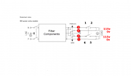
Tracing the wires in your schematic, this is what I get:
Tracing the wires in your schematic, this is what I get:
View attachment 468062
Use the schematic to draw the layout and then repost.
The LED is not connected to AC. It must be connected to DC with a resistor in series. Best leave connecting the LED until later, it is not needed for a correct working of the switches.
From the data sheet:
----------------------------------------------------
If the source voltage exceeds the rated
voltage, a ballast resistor is required.
The resistor value can be calculated by
using the formula in the Supplement.
----------------------------------------------------
For future searches on LED and resistor value, this is the formula to use:
R = (E - Vf) / If
Where:
R = resistor value (ohms)
E = source voltage (V)
Vf = forward voltage (V)
If = forward current (A)
Example, if:
Source voltage = 5V
Forward voltage = 1.9V (this is specified by LED)
Forward current = 20mA (this is specified by LED)
Then the correct resistor value is 155 ohm.
Additionally, the power rating of the resistor should be considered.
- The voltage across the resistor is (5.0V - 1.9V) = 3.1V
- Power across is (3.1V * 20mA) = 0.062W
- For safety, 2X the calculated value
- The resulting power rating is (0.062W * 2) = 0.124W or 1/4W resistor
The 20mA specification for a LED is usually the maximum continuous current.
For an indicator LED, this is usually too bright.
Expect 1mA to 3mA to give a more acceptable brightness for an indicator.
Using 50% of maximum resistor power rating is usually good for long term reliability.
Some locations inside amplifiers benefit from using much less than 50% of maximum rating. eg. the NFB resistors when output voltage is at peak can dissipate quite high powers and here using a power rating of ten times the peak power across the NFB would give a more linear output signal.
Hi Mark, looking at your diagram, should 115-0-115-0 read 0-115-0-115. So that 1 (P) connects to 115, and 4 (P) connects to 115 of the transformer.
View attachment 468062
Use the schematic to draw the layout and then repost.
The LED is not connected to AC. It must be connected to DC with a resistor in series. Best leave connecting the LED until later, it is not needed for a correct working of the switches.
From the data sheet:
----------------------------------------------------
If the source voltage exceeds the rated
voltage, a ballast resistor is required.
The resistor value can be calculated by
using the formula in the Supplement.
----------------------------------------------------
Attachments
Last edited:
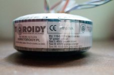

the Toroidy transformer seems to have a centre tapped Primary.
showing as 115-0-115Vac.
This works OK on 230Vac. all the prinary winding is in operation and you get the full 150VA rating.
For 115Vac supply you can only use half the winding. This reduces the ampere turns. The winding either runs at the same current to give half the rated VA, i.e. 75VA or it runs at double the current to deliver the full VA. It is unusual for the centre tapped winding to have a thick half and a thin half, but they do exist and would be marked to enable correct wiring at the lower voltage.
You need to identify what you have.
Andrew, absolutely right. I'm just realising now that you pointed this out. How do I use the full winding? (I take it for 115v, the 115-0 are used, leaving the other 115v wire unconnected).
When you say thick-half, thin-half, are you referring to the "0" green-yellow label? This is actually just one wire but is multi-coloured.
I updated the diagram.
When you say thick-half, thin-half, are you referring to the "0" green-yellow label? This is actually just one wire but is multi-coloured.
I updated the diagram.
the Toroidy transformer seems to have a centre tapped Primary.
showing as 115-0-115Vac.
This works OK on 230Vac. all the prinary winding is in operation and you get the full 150VA rating.
For 115Vac supply you can only use half the winding. This reduces the ampere turns. The winding either runs at the same current to give half the rated VA, i.e. 75VA or it runs at double the current to deliver the full VA. It is unusual for the centre tapped winding to have a thick half and a thin half, but they do exist and would be marked to enable correct wiring at the lower voltage.
You need to identify what you have.
Attachments
Pri: 115-0-115 red-blue-red
This to me is a 230Vac transformer.
You will not get full VA using 115Vac.
Ask Toroidy for confirmation of it's ability using 115Vac.
"0" green-yellow
connects to Chassis, at the transformer where the lead exits the insulation, using the shortest wire length.
This is the inter-winding screen connection. It couples very high frequency (VHF) interference to the screening Chassis and thence to "Earth" via capacitance coupling, virtually none through the PE wire (too much impedance).
Last edited:
- Status
- This old topic is closed. If you want to reopen this topic, contact a moderator using the "Report Post" button.
- Home
- Amplifiers
- Power Supplies
- How to hookup an illuminated power switch or button