Hello,
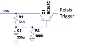
I’m using the small circuit below to delay a relay. The circuit 5V input of the circuit is delayed and then fed as trigger to a relay circuit.
The setup below doesn’t allow enough delay, so I updated the C1 capacitor to 470uF, now I’m only a second or two short of what I need.
The person I got this circuit from indicated that I should not use more than 470uF, I expect this is due the current flowing through the resistor.
Is there an easy way to add the 1-2 seconds delay?
Thanks and regards,
HJH
Attachments
I'm not sure if I understand you correctly. The BD139 is a transistor capable of a higher current.
You expect the current through the BC547C could be problematic?
One more vote for a 555 from me.
Definitely worth learning.
I control pretty much everything in a power supply with those. Delays, relay driving, voltage monitoring,... oscillators... You name it...
Anyways,
to design a simple one transistor delay circuit, we might want to have a bit more information about your actual relay itself.
For example, what is its coil resistance?
And what is the minimum switch on voltage of it?
Measure them, if not available from the data sheets.
Thx. A timer IC would be a good idea, but I'm unfortunately not that schooled in electronics to develop a complete circuit myself.
Increase C1. There is no reason why it can't be larger than 470uF. Also, if you show use some more of the circuit (exactly what happens after the transistor?) we may be able to help even more.
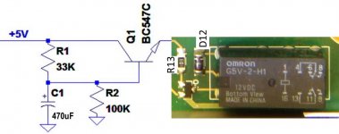
I have attached the circuit below. Including a picture of the Relay part of the circuit board I am attaching the delay to.
Unfortunately I do not have a diagram of the board I’m adding the delay to.
There is a control transistor in smd under diode d12. The 5V trigger is applied to the top side of r13. It is at 0V when the relay is off.
The output of the delay circuit is directly applied to the top of R13.
HJH
Unfortunately I do not have a diagram of the board I’m adding the delay to.
There is a control transistor in smd under diode d12. The 5V trigger is applied to the top side of r13. It is at 0V when the relay is off.
The output of the delay circuit is directly applied to the top of R13.
HJH
Attachments
The 5 volts is easily available. It’s a modified cd-player to DAC. The relay discussed is the output muting relay. Normally operated by the Kill signal of the Cd player.
I measured the voltage to be 3.9V that was originally supplier to the relay. I placed a 330 Ohms resistor after the delay scheme. This to be sure, but it should also work on 5V.
I just saw that I accidentally left the 330 Ohms resistor out in the drawing it is between the picture and the circuit, just before R13.
Didn't know that also playing around with the R values could be an option.
You could... and this is a simple approach... try adding a IN4148 diode in series with that 10k on the relay board. The diode would have to be between the resistor and the base of that transistor (in other words nick the print with a craft knive and add the diode over the break). Then just add a low voltage electroylitic (but it would need to be large for a reasonable delay, say a 2200/6.3 volt)
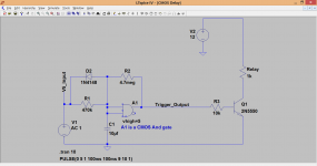
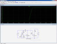
A much cleaner solution to all these, meaning cleaner in getting a sharp trigger pulse, would be to use 1 gate from a CMOS package. Minimal component count and a reliable and clean trigger. The transistor and cap method give a slow rise time and poorly defined relay close action because the voltage switch slowly.
This shows the idea. The transistor and so on is on your PCB. The delay is set by altering the cap + resistor to suit. The diode ensures the circuit is ready to work immediately following a quick on/off sequence. That is something the other circuits will struggle with.
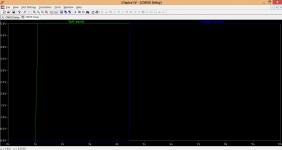
The green trace is the +5 volts appearing and the blue trace the trigger signal which appears some 4 seconds later.
A much cleaner solution to all these, meaning cleaner in getting a sharp trigger pulse, would be to use 1 gate from a CMOS package. Minimal component count and a reliable and clean trigger. The transistor and cap method give a slow rise time and poorly defined relay close action because the voltage switch slowly.
This shows the idea. The transistor and so on is on your PCB. The delay is set by altering the cap + resistor to suit. The diode ensures the circuit is ready to work immediately following a quick on/off sequence. That is something the other circuits will struggle with.
The green trace is the +5 volts appearing and the blue trace the trigger signal which appears some 4 seconds later.
Attachments
The 5 volts is easily available. It’s a modified cd-player to DAC. The relay discussed is the output muting relay. Normally operated by the Kill signal of the Cd player.
I measured the voltage to be 3.9V that was originally supplier to the relay. I placed a 330 Ohms resistor after the delay scheme. This to be sure, but it should also work on 5V.
I just saw that I accidentally left the 330 Ohms resistor out in the drawing it is between the picture and the circuit, just before R13.
Didn't know that also playing around with the R values could be an option.
R13 is just a 10k current limiting resistor in series with the base of the transistor. If you had more than 5 volts available then you could rig up another resistor in series with R13 and just connect a cap to the junction of these and ground. That would do the delay (its a simple version) with no real complexity... but you would need say 12v or higher to do that.
All R13 does is limit the base current. As long as there is enough then the transistor will switch. The exact amount of current needed depends on the gain of the transistor and so 10k is a safe value for any common transistor type. 10k, 20k, 5k. All would work just the same.
Preferably I would not make any modifications to the original relay board. There is not much space and SMD… I’m not that confident in soldering yet.
I like the solution you made with the CMOS AND gate. I found some info on the function of this device on the net (I have basic knowledge and a learning by doing).
The timing I expect would change by R1 and C1?
I found the 74HCT08 IC on the net. If I’m correct:
- 1a and 1b are connected together
- 1y is the trigger output
- The IC would need 5V to VCC and Gnd connected.
Whereby the function of the Gate is a clear “on” trigger, whereas the transistor voltage is indeed constantly climbing until it reaches 5v
The current setup I have (as in the picture attached in the previous post) gives a delay of around 13 seconds. I need minimum 15 seconds.
@ Elvee,
Is there a way to calculate the time?
Attachments
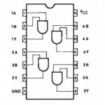
Yes that's it, and you can use any one of the four gates in the package. The other unused inputs should not be floating but all tied either high or low. That is easy to do... just connect the output of one to the inputs of the next and so on in a chain. Or just connect to ground. The outputs are fine floating.
The 4.7meg (not critical) ensure the super clean switching action by adding "hysteresis".
I was actually thinking of the 4000 series of IC's, 4081 I think is the AND gate but the 74HCT should be fine too.
The 4.7meg (not critical) ensure the super clean switching action by adding "hysteresis".
I was actually thinking of the 4000 series of IC's, 4081 I think is the AND gate but the 74HCT should be fine too.
- Status
- This old topic is closed. If you want to reopen this topic, contact a moderator using the "Report Post" button.
- Home
- Amplifiers
- Power Supplies
- Delay circuit, more delay time needed