I wasn't sure where to post this question.
When reading this it's best to remember I'm a complete electronics beginner.
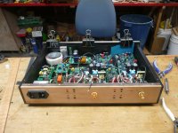
I have been building my sister a set of speakers, speaker stands & amp/crossover for some time now, the speakers are finished, the stands are finished and I was just putting the amp in the final painted case to do the last quick check before taking it all over to the sisters. I have done extensive testing and had the amp all working as planned but an ongoing issue that I have battled with over many months has reared it's ugly head again (I thought I had it licked)
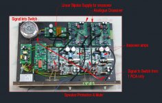
I have built a Signal Switch based around the Rod Elliot design to turn the amp/crossover on/off. The problem I am having is that the switch will not turn off once the switch input resistor is of a low enough value that is needed for detection sensitivity. After many many hours of trying to work out what the problem was I discovered that when the switch tries to turn off a small negative DC voltage appears at the switch signal input. After much mucking around I deduced ( I could be wrong) that what is happening is when the amp tries to turn off the transformer is causing a voltage to go through the linear supply then through the crossover, back to the RCA input and on to the signal switch input, and this is forcing the switch back on.
When I was testing I could not find any AC at the signal switch input on turn off so though the problem must have been elsewhere, It was only when I turned the multimeter to DC that I found the DC appearing at the Switch input/Crossover Input.
Initially I tried 3 different Linear supplies with the same result, then I tried a SMPS and the problem disappeared, which lead me to believe it was the transformer causing the problem. As I didn't want to use a SMPS to power the crossover I persisted and eventually tried Star grounding and that seemed to solve the problem, but it hasn't
I could revert to the SMPS to power the crossover, but I dont want to
I could remove the Signal Switch but, I dont want to
It seems to me I need to somehow block the DC getting back to the switch but have no idea how to go about it.
When reading this it's best to remember I'm a complete electronics beginner.
I have been building my sister a set of speakers, speaker stands & amp/crossover for some time now, the speakers are finished, the stands are finished and I was just putting the amp in the final painted case to do the last quick check before taking it all over to the sisters. I have done extensive testing and had the amp all working as planned but an ongoing issue that I have battled with over many months has reared it's ugly head again (I thought I had it licked)
I have built a Signal Switch based around the Rod Elliot design to turn the amp/crossover on/off. The problem I am having is that the switch will not turn off once the switch input resistor is of a low enough value that is needed for detection sensitivity. After many many hours of trying to work out what the problem was I discovered that when the switch tries to turn off a small negative DC voltage appears at the switch signal input. After much mucking around I deduced ( I could be wrong) that what is happening is when the amp tries to turn off the transformer is causing a voltage to go through the linear supply then through the crossover, back to the RCA input and on to the signal switch input, and this is forcing the switch back on.
When I was testing I could not find any AC at the signal switch input on turn off so though the problem must have been elsewhere, It was only when I turned the multimeter to DC that I found the DC appearing at the Switch input/Crossover Input.
Initially I tried 3 different Linear supplies with the same result, then I tried a SMPS and the problem disappeared, which lead me to believe it was the transformer causing the problem. As I didn't want to use a SMPS to power the crossover I persisted and eventually tried Star grounding and that seemed to solve the problem, but it hasn't
I could revert to the SMPS to power the crossover, but I dont want to
I could remove the Signal Switch but, I dont want to
It seems to me I need to somehow block the DC getting back to the switch but have no idea how to go about it.
Attachments
project 104? (no omissions or substitutions?)
are you sending a signal line(RCA) into the trigger input of the mute circuit?
sorry for the questions but although the supplied pic's are great it's not like being there to look things over.
the different behavior with the two different supplies at shutoff is linears fade whereas switchmodes drop like a brick.
oh and for someone who considers himself a newbie from the pic's your a newb with pride! (nice build)
Last edited:
Please don't pull your hair out, you only get one set.
Sounds to me like the transformer is inducing current flow via magnetism into the chassis and the cable is picking it up somehow... goodness knows how.
You can also always block DC with a capacitor, any kind, in line with the switch, as long as its rated for the voltages.
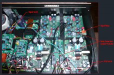
EDIT: I can see that you've tried lifting the wire up from the bottom of the case in one of the pics. I would therefore go ahead and try putting a capacitor in between the sense circuit and the RCA connector at the back. If all the circuit needs is an audio signal and no DC component to switch on and off then putting in a dc blocking capacitor will fix the problem/issue of DC being picked up by the wire.
Failing that it could be an earthing issue on the switching circuit.
Btw nicely done star grounding. Nothing about this project must've been cheap.
Sounds to me like the transformer is inducing current flow via magnetism into the chassis and the cable is picking it up somehow... goodness knows how.
You can also always block DC with a capacitor, any kind, in line with the switch, as long as its rated for the voltages.
EDIT: I can see that you've tried lifting the wire up from the bottom of the case in one of the pics. I would therefore go ahead and try putting a capacitor in between the sense circuit and the RCA connector at the back. If all the circuit needs is an audio signal and no DC component to switch on and off then putting in a dc blocking capacitor will fix the problem/issue of DC being picked up by the wire.
Failing that it could be an earthing issue on the switching circuit.
Btw nicely done star grounding. Nothing about this project must've been cheap.
Last edited:
project 104? (no omissions or substitutions?)
are you sending a signal line(RCA) into the trigger input of the mute circuit?
sorry for the questions but although the supplied pic's are great it's not like being there to look things over.
the different behavior with the two different supplies at shutoff is linears fade whereas switchmodes drop like a brick.
oh and for someone who considers himself a newbie from the pic's your a newb with pride! (nice build)
No, its project 38, which has been modified slightly as suggested by Bob Ellis to stop channel cross-talk. I started with Rod Elliot's board but had the same issues and then got some boards made. The changes are only minor.
I am using the single ended incoming signal to turn the amp/crossover on, which is the blue wire in the photo. I had a nice neat setup but when things went haywire I started trying anything to get it to work, hence the stray blue wire.
I'm great with electronics as long as nothing goes wrong
Please don't pull your hair out, you only get one set.
Sounds to me like the transformer is inducing current flow via magnetism into the chassis and the cable is picking it up somehow... goodness knows how.
You can also always block DC with a capacitor, any kind, in line with the switch, as long as its rated for the voltages.
EDIT: I can see that you've tried lifting the wire up from the bottom of the case in one of the pics. I would therefore go ahead and try putting a capacitor in between the sense circuit and the RCA connector at the back. If all the circuit needs is an audio signal and no DC component to switch on and off then putting in a dc blocking capacitor will fix the problem/issue of DC being picked up by the wire.
Failing that it could be an earthing issue on the switching circuit.
Btw nicely done star grounding. Nothing about this project must've been cheap.
The case is made of plywood with carbon fibre laminated on the outside for shielding and strength, I don't think the case is transferring the DC signal.
I have tried a 1uf & then a 10uf bipolar capacitor in series with the signal but it didn't help.
I could probably setup some relays to block the transformer supply but at this late stage trying to cram something else into the case is not going to happen.
so it's not turning off after 20 minutes without signal?
if dc is appearing at the input RCA jack there's something wrong for sure.
What happens is when it switches the power off there's an instant very small surge of -DC that comes back thru the crossover input that runs back to the switch and turns it back on, it just keeps cycling off-on-off-on etc.
I can stop this from happening by lessening the sensitivity (higher value resistor) of the switch but the sensitivity needs to be so low that the music signal that's needed to turn it back on is too high.
Last edited:
are you switching the ac or dc side of your supply?(you may also give thought to switching the input signal line after your trigger point connection in order to prevent the supply collapsing from creating a state change appearing at the sense line) provided you have means of sequencing the timing of the relays as in signal line first then power and the inverse at power up
Last edited:
you may also give thought to switching the input signal line after your trigger point connection in order to prevent the supply collapsing from creating a state change appearing at the sense line
Great minds think alike, it took you 1 night and me 6 months to think of it though
I'm going to try and use a small signal relay to cut the music signal at the crossover input so it cant get back to the signal switch one it turns off. I should be able to use the signal switch itself to drive the relay.
Thanks
PS I'm cutting the AC, but have a small SMPS driving the signal switch that is always on.
I'd say that this circuit isn't liking the mains for some reason is its filtering cap ok? Does a 0.1uF ceramic cap across the filtering cap fix this issue?, a good approach would be the relay idea, isolate those lines. What is your source like btw? Is it 2 pronged? Could be a ground loop coming from another leaky smps in your transport?
Failing that there is a capacitor inside the crossover which is discharging and turning the amp/crossover back on, completing the evil cycle of doom.
.ƃuıɥʇ ɟo ʇɹos sıɥʇ ʇnoqɐ ƃuıʎɹɹoʍ ǝq oʇ ʇɹoɥs ooʇ s,ǝɟıl.
This sure is a complicated way to turn on an amp.
Also I didn't know carbon fiber was conductive, the more you know!
Last edited:
I think I've fixed the "Evil Cycle of Doom" more testing tonight when I have time to sit and listen.
I ended up powering the the signal relay from one of the speaker protection boards as I realised if the signal switch goes haywire at any stage and my sister uses the power button to turn the unit on the signal relay would not operate. Conveniently I had the relay board already made for another purpose, you can never have too many bits and pieces
Thanks for the help gentlemen.
more testing tonight when I have time to sit and listen.I ended up powering the the signal relay from one of the speaker protection boards as I realised if the signal switch goes haywire at any stage and my sister uses the power button to turn the unit on the signal relay would not operate. Conveniently I had the relay board already made for another purpose, you can never have too many bits and pieces
Thanks for the help gentlemen.
Attachments
so... do you still have hair left...or are you still having grief...?
What little I started with I still have
It's all good, the solution may not be ideal but it works & I couldn't hear any difference.
The project has been delived to my sister & I'm very glad to see it gone, took way longer than expected.
Thanks for the help
- Status
- This old topic is closed. If you want to reopen this topic, contact a moderator using the "Report Post" button.
- Home
- Amplifiers
- Power Supplies
- Pulling My Hair Out