I am building a wireless charging station and since I am new to high frequency switching I would like to discuss the design here with someone with more experience. I will do the testing and post the results here and hopefully my results can be used by others wanting to do something similar.
The plan is to charge 10 NIMH cells in a remote through inductive coupling from a base station. The reason for using NIMH cells is that thay are safer. Also, when it comes to volume they have about the same energy density as LiPo.
There will be a communication system between the remote and the base station based on 2,4GHz RF link.
I have bought a transmitter and receiving coil from Würth
http://katalog.we-online.de/pbs/datasheet/760308111.pdf
http://katalog.we-online.de/pbs/datasheet/760308201.pdf
The distance between the coils will be about 5 mm and I am hoping to be able to transfer around 8W maximum for a charge time of about 4-5 hours.
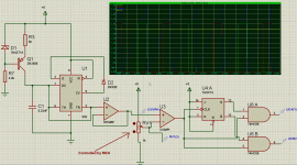
So far I have built this PWM circuit where I can adjust both frequency and duty cycle. The logic at the end extract every second pulse and feed them to two inputs on the gate-driver (Si8233). This works fine and I can adjust duty cycle from 0 to almost 100%

The plan is to adjust the duty cycle depending on how much power the charging circuit in the remote needs.
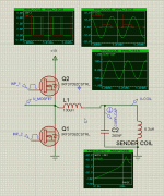
The output stage I want to try first looks like this:

I have only simulated this so far and it seems to be working there. It consists of only 5 components. Two mosfets, coil L1, Cap C2 (MKP) and the sender coil.
The sender coil is optimized to work at 125kHz so I have used a 260nF cap in parallel with the coil to make a resonant tank. The resonant frequency is 1/(2*PI*SQRT(L*C))
The value of L1 was found by simulating various values and see which value gave the higest voltage over the sending coil.
Does anyone have a formula for the value of this coil?
What about the output stage alltogether? Will it go up in smoke?
I have considered adding two more mosfets and build a H-bridge. In that case I suppose I can skip L1 and use only C2 in parallel with the sender coil.
All help and tips appreciated.
The plan is to charge 10 NIMH cells in a remote through inductive coupling from a base station. The reason for using NIMH cells is that thay are safer. Also, when it comes to volume they have about the same energy density as LiPo.
There will be a communication system between the remote and the base station based on 2,4GHz RF link.
I have bought a transmitter and receiving coil from Würth
http://katalog.we-online.de/pbs/datasheet/760308111.pdf
http://katalog.we-online.de/pbs/datasheet/760308201.pdf
The distance between the coils will be about 5 mm and I am hoping to be able to transfer around 8W maximum for a charge time of about 4-5 hours.
So far I have built this PWM circuit where I can adjust both frequency and duty cycle. The logic at the end extract every second pulse and feed them to two inputs on the gate-driver (Si8233). This works fine and I can adjust duty cycle from 0 to almost 100%

The plan is to adjust the duty cycle depending on how much power the charging circuit in the remote needs.
The output stage I want to try first looks like this:

I have only simulated this so far and it seems to be working there. It consists of only 5 components. Two mosfets, coil L1, Cap C2 (MKP) and the sender coil.
The sender coil is optimized to work at 125kHz so I have used a 260nF cap in parallel with the coil to make a resonant tank. The resonant frequency is 1/(2*PI*SQRT(L*C))
The value of L1 was found by simulating various values and see which value gave the higest voltage over the sending coil.
Does anyone have a formula for the value of this coil?
What about the output stage alltogether? Will it go up in smoke?
I have considered adding two more mosfets and build a H-bridge. In that case I suppose I can skip L1 and use only C2 in parallel with the sender coil.
All help and tips appreciated.
A friend of mine is something of a wireless power expert. Miniature wireless power demonstrator | Marko's science site.
A friend of mine is something of a wireless power expert. Miniature wireless power demonstrator | Marko's science site.
Thank you for that link. It was similar to what I want to achieve, but I think he's setup is optimized for longer distances.
I did some tests with the output stage shown in my previous post, but that was not successful. I moved on to drive the L-C tank directly from a full H-bridge and that was much better. The primary coil now runs from a 24V supply at 125kHz. So far I am able to transfer 10W of power over a 5mm distance with an efficiency of 46% from input to output.
coils are still lossy at those freqs. moving up in freq you could ugo to 6.78Mhz (ISM freq). the coils can be flat pcb wide traces, and as penetration depth is around 30 microns 10z copper is OK. use mica caps for resonance. you can control the power by controlling the supply voltage of the rf stage using a dcdc switcher. coil Q's of over 200 area easily made.
so most of the losses will be in the driver and post rectification.
otherwise classE driving the coils at 125khz is an option, but that's only working for 50% duty cycle, so you have to control the dc supply again.
so most of the losses will be in the driver and post rectification.
otherwise classE driving the coils at 125khz is an option, but that's only working for 50% duty cycle, so you have to control the dc supply again.
I prefer to stay away from RF as it tends to complicate stuff. Also the coils I am using are optimized for 100kHz to 300kHz with Q factor of about 80 in that range.
Using class E at 125kHz is an interesting option and adjusting the supply voltage is not a problem. The H-brigde I am using now seems like overkill. Could you give me some hints how to test a class-E? The coil data is in the link in my first post.
Using class E at 125kHz is an interesting option and adjusting the supply voltage is not a problem. The H-brigde I am using now seems like overkill. Could you give me some hints how to test a class-E? The coil data is in the link in my first post.
- Status
- This old topic is closed. If you want to reopen this topic, contact a moderator using the "Report Post" button.