Dear All,
Just developed a very simple power supply to drive a relay, however it is not working as it should. The relay is clicking as being on AC
In my equipment I have 5 Volts AC which I'm using, in the schematic these are "F1" and "F2".
This 5V AC is fed via a Bridge rectifier to a TS2940 regulator, supported by two tantalum capacitors. This to have a very small and simple regulated power supply.
I've attached the circuit I made.
Te components used are:
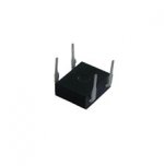
- Bridge rectifier: B250C1000 (picture of type attached)
- 10 uF Tantalum caps, (both the same, these are according to the datasheet of the regulator)
- TS2940 - 1A Ultra Low Dropout Fixed Positive Voltage Regulator, supply 3.3V
- Zetler AZ822–2C–3DSE Relais.
Can anybody support me in what I'm doing wrong here?
Thanks a lot in advance!
Regards, HJH
Just developed a very simple power supply to drive a relay, however it is not working as it should. The relay is clicking as being on AC
In my equipment I have 5 Volts AC which I'm using, in the schematic these are "F1" and "F2".
This 5V AC is fed via a Bridge rectifier to a TS2940 regulator, supported by two tantalum capacitors. This to have a very small and simple regulated power supply.
I've attached the circuit I made.
Te components used are:
- Bridge rectifier: B250C1000 (picture of type attached)
- 10 uF Tantalum caps, (both the same, these are according to the datasheet of the regulator)
- TS2940 - 1A Ultra Low Dropout Fixed Positive Voltage Regulator, supply 3.3V
- Zetler AZ822–2C–3DSE Relais.
Can anybody support me in what I'm doing wrong here?
Thanks a lot in advance!
Regards, HJH
Attachments
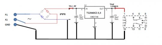
Just my first thought, but looks like you don't have a smoothing capacitor in
output of the rectifier bridge, C1 is in correct location but too small for this purpose,
and is probably there to maintain regulator stability.
Try placing something like a 470uF electrolytic capacitor across the output
of the bridge this will store more energy and maintain the voltage into the regulator.
The new capacitor is effectively in parallel with C1, but C1 and C2 should be
positioned close the regulator for stability reasons.
Regards, Symon
Thanks for the quick responses this really helps!
I understand that I should "smooth" the output of the Bridge before it is entering the 2940.
The reason why I kept the C1 and C2 this small is that I need a fast power off for the relay when I disconnect the AC (which is a transformer output).
Would a larger Capacitor not store so much energy that the relay would be delayed for a few seconds?
The Tantalum capacitors are both within 0.5 cm of the 2940, so this should be Ok.
I attached the datasheet that I'm using, on page 3 is the scheme I'm using, there the 10 uF's are listed. Strange
One other thing I just found is that I see in some circuits a diode across the relay coil, would this be an option?
Attachments
Last edited:
Those 10uF caps you see are for stability, but they assume the DC you are`regulating is smooth enough already .
Otherwise you are`feeding it full wave rectfied (but unfiltered) AC; the`regulator can't magically create a DC voltage which is not there between peaks.
As of the turn off time constant, calculate it using the filter capacitance and the`relay coil resistance.
I would not choose that shorter than a second.
Larger values of C1 will hold the relay on longer when power is shut off. As you found out 10uF is too small and does not work. Try 470uF and if the drop out time is too long then try 220uF and finally 100uF. Eventually the capacitance reduction will be too much and the relay will not close properly. Hopefully one of the capacitance values turns on the relay reliably while still not holding it on too long when power drops.
Regarding the diode across the relay coil, yes that is usually added to clamp the coil voltage when shutting the relay off.
Regarding the diode across the relay coil, yes that is usually added to clamp the coil voltage when shutting the relay off.
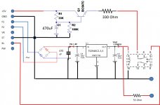
That indeed worked , I put a 470 uF across C1 and now the relay holds perfectly. The shutdown time is also still short and no problem for what I'm doing.
However, a next question arose.....
The connections I made are F1 and F2 for the AC and the GND. The relay works, but one resistor on the main circuit board gets very hot and smelly....
When disconnecting the GND lead everything still works with only F1 and F2 connected, and the resistor does not get hot.
Somehow I cannot connect both the grounds together? The - (ground) of the Relay power supply and the Ground of the equipment I'm building it into.
, I put a 470 uF across C1 and now the relay holds perfectly. The shutdown time is also still short and no problem for what I'm doing.However, a next question arose.....
The connections I made are F1 and F2 for the AC and the GND. The relay works, but one resistor on the main circuit board gets very hot and smelly....
When disconnecting the GND lead everything still works with only F1 and F2 connected, and the resistor does not get hot.
Somehow I cannot connect both the grounds together? The - (ground) of the Relay power supply and the Ground of the equipment I'm building it into.
For low fi audio I have seen a recommendation of 1000uF (1mF) per ampere of load.
For Higher Fi use 2mF/A
For highest Fi consider 5mF/A
For a relay 1mF/A is perfectly adequate.
What is the current draw of the load?
if the regulator wastes 1mA and the relay uses 45mA then the capacitor required is very approximately {0.001+0.045} * 1 = 46uF
use 47uF or 100uF.
If it's too low the ripple will cause the regulator to drop out during the dips in the input voltage.
The relay won't mind.
If you had an oscilloscope you can check for drop out, particularly when mains voltage is low.
But as I said a relay won't complain.
However a relay supply that uses the minimum smoothing capacitance to ensure reliable operation will release more quickly when mains fails.
This is sometimes referred to as instant off.
Too big a cap and instant off can be many seconds !
In my equipment
What the h*ck is said equipment?one resistor on the main circuit board gets very hot and smelly....
the resistor does not get hot.
the equipment I'm building it into.
What the h*ck is "the" resistor?
Schematic? .... Value? ....
You are in the wrong Forum, ask again in Divination&Fortune_Telling.com.ts in Transylvania


Without the GND to the relais board everything works OK.What the h*ck is said equipment?
What the h*ck is "the" resistor?
Schematic? .... Value? ....
You are in the wrong Forum, ask again in Divination&Fortune_Telling.com.ts in Transylvania
So ,what the h*ck, who cares
Mona
Guys, sorry, just trying to learn here.
Maybe a little to vague in my previous post, but I thought it was not needed to provide all the other details of the project.
To go short I'm making a small circuit board to prevent a "pop" when turning of my cd player. On this board a second scheme is present to delay the muting relay on, due to tubes heating up.
So the muting relay needs to be turned off immediately when power is turned off and is delayed when power is turned on. To turn the player on and off I'm switching mains.
The relay in the circuit the post is started with is in the power line of the muting relay. The power to the muting relay itself is delayed. For this a +5V and Ground connection is used to integrate a delay circuit in the power line of the muting relay.
Both schemes are on 1 small circuit board I developed. Therefore I have on this board a 5V AC and a +5V and GND connection.
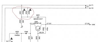
By connecting all (5V AC and DC and GND) I have a resistor 3251 next to the connector (The red circled one in the drawing "resistor") getting very hot. F1 and F2 are direct connections to the transformer. This is part of the CD-4000 of Marantz.
I also attached my own developed scheme. Sorry, no pro lay-out. The improvement of the capacitor is in this scheme.
Hope this made it more clear
Maybe a little to vague in my previous post, but I thought it was not needed to provide all the other details of the project.
To go short I'm making a small circuit board to prevent a "pop" when turning of my cd player. On this board a second scheme is present to delay the muting relay on, due to tubes heating up.
So the muting relay needs to be turned off immediately when power is turned off and is delayed when power is turned on. To turn the player on and off I'm switching mains.
The relay in the circuit the post is started with is in the power line of the muting relay. The power to the muting relay itself is delayed. For this a +5V and Ground connection is used to integrate a delay circuit in the power line of the muting relay.
Both schemes are on 1 small circuit board I developed. Therefore I have on this board a 5V AC and a +5V and GND connection.
By connecting all (5V AC and DC and GND) I have a resistor 3251 next to the connector (The red circled one in the drawing "resistor") getting very hot. F1 and F2 are direct connections to the transformer. This is part of the CD-4000 of Marantz.
I also attached my own developed scheme. Sorry, no pro lay-out. The improvement of the capacitor is in this scheme.
Hope this made it more clear
Attachments
Last edited:
So you like to blow-up a powersupply
F1 F2 are for the heater of the display, drawing 70..80mA more for that relais cicuit can very well burn the transfo windings.
The heater if kept at -23V from ground (-28V supply minus 5V zener) and you almost shortcicuit it to ground.Not only overheating a resistor but everything from the -28V supply.
Mona
Thanks for your reply
The display is not connected anymore, as I rebuild the player to a DAC by adding a SPDIF input board.
I was not aware about the low available current of F1 and F2, I'm not able to find anywhere what the specs of the transformer are The part number according to the manual is: 4822 146 11031, but it doesn't return specs on the net.
The only parts that will be connected to F1 and F2 are in the scheme I started the post with. So relay, the capacitors and Power regulator.
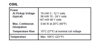
I attached the specs of my relay coil also. Would this setup be possible without damage (with disconnected display)? I understand that the regulator Quiescent Current of 100uA is the current consumed. I can then perform the calculation as explained by Anderew.
However I do understand that both GND's are not the same and that I'm making a short circuit. This is then in line with a working relay with only F1 and F2 connected.
Regards, HJH
The display is not connected anymore, as I rebuild the player to a DAC by adding a SPDIF input board.
I was not aware about the low available current of F1 and F2, I'm not able to find anywhere what the specs of the transformer are
The part number according to the manual is: 4822 146 11031, but it doesn't return specs on the net.The only parts that will be connected to F1 and F2 are in the scheme I started the post with. So relay, the capacitors and Power regulator.
I attached the specs of my relay coil also. Would this setup be possible without damage (with disconnected display)? I understand that the regulator Quiescent Current of 100uA is the current consumed. I can then perform the calculation as explained by Anderew.
However I do understand that both GND's are not the same and that I'm making a short circuit. This is then in line with a working relay with only F1 and F2 connected.
Regards, HJH
Attachments
- Status
- This old topic is closed. If you want to reopen this topic, contact a moderator using the "Report Post" button.
- Home
- Amplifiers
- Power Supplies
- Simple power supply for a Relais