The "r_dynamic" resistances are of course already incorporated into the diode .MODEL equations
I suspect this may be a clue...
I have updated the folder to include a model of a DPDT switch bypassing two diodes as suggested by Mark. Comments/corrections appreciated. Previous link should work but just in case you can click here to download it. Perhaps this power relay would be suitable for this application. I've used key characteristics from its data sheet in the model.
In the hysteresis schematic I think it unwise to model D6-D8 as SPICE default diodes. You want voltage dropper diodes D7 & D8 to be small-area devices, so their Vfwd @ 5mA is large; the default diode doesn't do that. You want LED D6 to have the Vfwd of an actual Aluminum-Indium-Gallium-Phosphide light emitting diode; the default diode doesn't do that.
I also think it best to attach the R_currentlimit--LED network directly across the main 1000uF bulk capacitor; that way when the relay operates, they don't see a jump-up in voltage, causing a jump-up in pulldown current.
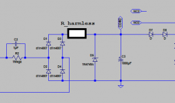
Finally, since the hysteresis schematic presupposes a brand new PCB layout anyway, why not explore the idea of adding a harmless current-peak-smearing resistor "R_harmless" somewhere or other, perhaps as below? One more resistor, so what.
Does there exist a value of R_harmless which reduces the peak current in C2 by a noteworthy amount, yet doesn't do substantial harm to the final output voltage across the 1000uF capacitor after 500 AC mains cycles? If so, why not put it in, and feel good about spending 2 pence on a resistor that exponentially prolongs the life of C2?
Or, says the devil's advocate, perhaps not. Perhaps the 3 Watt, 220 ohm resistor already provides all possible benefits, such that adding R_harmless actually makes things worse instead of better?
I also think it best to attach the R_currentlimit--LED network directly across the main 1000uF bulk capacitor; that way when the relay operates, they don't see a jump-up in voltage, causing a jump-up in pulldown current.
Finally, since the hysteresis schematic presupposes a brand new PCB layout anyway, why not explore the idea of adding a harmless current-peak-smearing resistor "R_harmless" somewhere or other, perhaps as below? One more resistor, so what.
Does there exist a value of R_harmless which reduces the peak current in C2 by a noteworthy amount, yet doesn't do substantial harm to the final output voltage across the 1000uF capacitor after 500 AC mains cycles? If so, why not put it in, and feel good about spending 2 pence on a resistor that exponentially prolongs the life of C2?
Or, says the devil's advocate, perhaps not. Perhaps the 3 Watt, 220 ohm resistor already provides all possible benefits, such that adding R_harmless actually makes things worse instead of better?
Attachments
Last edited:
You want voltage dropper diodes D7 & D8 to be small-area devices
I don't follow you, but have changed them to 1N4148 diodes (200mA rating).
You want LED D6 to have the Vfwd of an actual Aluminum-Indium-Gallium-Phosphide light emitting diode; the default diode doesn't do that.
Good point. I have replaced it with
.model LTLCR5800 D(Vfwd=2.1 Ilimit=50m Vrev=5 mfg=Vishay type=LED)
LTspice has a hiccup when the voltage gets to 2.1V suggesting the model may have issues (no surprise) but eventually things continue.
Finally, since the hysteresis schematic presupposes a brand new PCB layout anyway, why not explore the idea of adding a harmless current-peak-smearing resistor "R_harmless" somewhere or other, perhaps as below? One more resistor, so what.
Does there exist a value of R_harmless which reduces the peak current in C2 by a noteworthy amount, yet doesn't do substantial harm to the final output voltage across the 1000uF capacitor after 500 AC mains cycles? If so, why not put it in, and feel good about spending 2 pence on a resistor that exponentially prolongs the life of C2?
Or, says the devil's advocate, perhaps not. Perhaps the 3 Watt, 220 ohm resistor already provides all possible benefits, such that adding R_harmless actually makes things worse instead of better?
A 2.75K resistor could be used to reduce the current across C2 but at the "expense" of longer switch delay. If one wanted a similar switch delay then C2 needs to increase and the current across it rises accordingly...R1 could be used to effect the same change. In either case the power dissipation required seems very high for relatively modest gains in lowering peak current across C2. ?
(linked model updated)
That's the nature of design; you make a change, try it out, and decide whether the results please you or not. If yes, you consider keeping the change. If no, you throw it away.
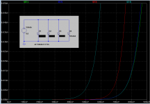
All other things being equal, diode current is proportional to junction area. So to get a big Vfwd at a given current, you want a small junction area. Usually people want the opposite: a small Vfwd at a given current, which calls for a large junction area. That's one reason why 10 ampere diodes cost more than 1 ampere diodes: the semiconductor ingot inside, is about 10x bigger.
In your case, you seek diodes whose Vfwd is relatively large when conducting a small current, about oh, let's just say, 20% of Relay_Pull_In_Current. So you want diodes with small junction areas. Stay away from 10 amp diodes and focus on those rated for less than an ampere. I simulated four plain ordinary silicon diodes (not "fast recovery", not Schottky, not Germanium) that happen to be present in my LTSPICE diode library file standard.dio. You want the green one, the one whose Vfwd is biggest.
You may even decide that you prefer to use (X number of LEDs in series), instead of (Y number of silicon diodes in series), to get the voltage drop / hysteresis you seek. Totally your call.
Attachments
One other question: if one were to take the time to redesign the board, why would they ever use resistors rather than an NTC? The resistors take up a lot of real estate which would perhaps be better used for, say, the requisite fuse (perhaps room for two for those using dual transformers)...
One other question: if one were to take the time to redesign the board, why would they ever use resistors rather than an NTC? The resistors take up a lot of real estate which would perhaps be better used for, say, the requisite fuse (perhaps room for two for those using dual transformers)...
Because the NTCs will decrease their resistance the moment current passes through and temp increases.
The resistors were employed to constantly limit the current momentarily, just enough to charge the main caps to a pre-determined level.
I believe the new boards have the option to use NTC so by all means do. The idea was to serve those whom would like to use resistors or NTCs, unless real estate is a problem for your application.
NTCs work better than fixed resistors.
1.) because they become self preserving in the event that the bypass relay fails to close.
2.) because they decrease in resistance as the current spike continues and thus allow a tapering of current increase to compensate for the reducing back emf. This gives closer to a constant current effect during start up.
But, there is a big downside to NTCs, cost.
There does not appear to be a big energy absorbing NTC that has resistances in the range 20r to 100r.
Fixed resistors can be series connected to achieve these higher values of current limiter.
How many CL60 (or equivalent) are required for a 60ohm limiter?
How much do they cost in the UK?
BTW, I have used fixed resistors in the range from 40r to 140r as current limiters in various power amplifiers. 15r does not limit sufficiently at the UK's 240Vac.
Douglas Self gives several reasons in his book APADH6e.One other question: if one were to take the time to redesign the board, why would they ever use resistors rather than an NTC?
I'll bet you can come up with a couple of them yourself, just by thinking about it for 15 minutes, even before you start reading.
Self does an excellent job reminding you why you learned "ELI the ICE man" (a mnemonic taught in university AC Circuits classes to remember reactive phase shift). It turns out to be crucial when building and testing inrush current limiters for a >500VA power transformer feeding huge downstream filter capacitors. You haven't really tested your softstart circuit until you've switched it on at every possible phase angle of the mains sinewave. Surprisingly (?), some phase angles are worse, much worse, than others. Those are the phase angles at which your customers will switch-on their equipment, thereby popping the fuse, burning the transformer, etc. By Murphy's Law.
He also offers some thought-provoking opinions on the question: when using several 5 watt resistors to create a higher-power resistor for inrush current limiting, is it preferable to connect the individual resistors in series, or in parallel? What are the pros and cons of each?
Last edited:
the second link devices will not do.
A pair giving 66r with 240Vac UK supply will draw ~ 4Aac. They are rated as 2.5A
A pair for one transformer comes to £3.48 That is not cheap for an unsuitable NTC.
The Ametherm's from Mouser might do, but again multiples will probably be required to give adequate current rating and resistance.
The Ametherm seem to be quite a bit cheaper.
Last edited:
I prefer the series connected resistors. The thicker wire of a lower resistance is possibly more robust and should tolerate overload better.Douglas Self gives several reasons in his book APADH6e.........................
He also offers some thought-provoking opinions on the question: when using several 5 watt resistors to create a higher-power resistor for inrush current limiting, is it preferable to connect the individual resistors in series, or in parallel? What are the pros and cons of each?
If using 10r 5W resistors and need 40r, then 4 off 10r will have a nominal current rating of 0.7A, and will have to tolerate 6Aac at start up.
Wired as parallel resistors using 4off 160r will have the same 0.7A current rating. Will the fine wire tolerate a start up current of 6A?
NTCs can ONLY be operated in series.
Last edited:
I will have to look at that section of the book. We've discussed the issue of immediate PWR_ON, PWR_OFF and then PWR_ON and the lack of time (even if bypassed) for the NTC ICL to cool. It would be fine if the "on" period were long enough for the NTC to be bypassed and cooled but immediate recycling would present a problem. Then there's the fact that they get very hot - I generally don't like touching anything mains related when the power is on ;-)
I've updated the folder to include models (with the suffix -ntc) using NTC ICLs. The models use the EPCOS 33R but can be modified to suit taste - EPCOS provide a range Spice models (they're in ntc_20130313.lib) and so modelling with them is easier. Change as you see fit.
I've updated the folder to include models (with the suffix -ntc) using NTC ICLs. The models use the EPCOS 33R but can be modified to suit taste - EPCOS provide a range Spice models (they're in ntc_20130313.lib) and so modelling with them is easier. Change as you see fit.
I prefer the series connected resistors. The thicker wire of a lower resistance is possibly more robust and should tolerate overload better.
If using 10r 5W resistors and need 40r, then 4 off 10r will have a nominal current rating of 0.7A, and will have to tolerate 6Aac at start up.
Wired as parallel resistors using 4off 160r will have the same 0.7A current rating. Will the fine wire tolerate a start up current of 6A?
NTCs can ONLY be operated in series.
Are you saying that the current flow through each resistors will be the same for a 4-series 10R 5W resistor and a 4-parallel 160R 5W resistors?
The effective resistance of both sets are the same, 40r.
The current through both sets are the same, the heating in both sets are the same.
Keep in mind we are dealing with 50/60Hz. Inductance (due to helical turns) and other impedances are virtually irrelevant to the resistor elements.
The current through both sets are the same, the heating in both sets are the same.
Keep in mind we are dealing with 50/60Hz. Inductance (due to helical turns) and other impedances are virtually irrelevant to the resistor elements.
A soft start with paralleled resistor arrangement cannot use paralleled NTCs..........................
NTCs can ONLY be operated in series.
This is not an option.
The soft start would need series connected resistive elements to allow NTCs or fixed value resistors to be chosen.
the second link devices will not do.
A pair giving 66r with 240Vac UK supply will draw ~ 4Aac.
Surely that assumes an infinitely sized capacitor bank. Of course one needs to size the NTC to the capacitance being charged. The 33R EPCOS NTCs I linked to - merely as I know you have an issue ordering from Mouser UK - have a rating of 23.8J equating to 900uF at 230V.
And presumably there's nothing to stop one placing NTCs in parallel in a circuit. Rather, isn't the issue is finding samples with large enough 25C resistance such that their parallel resistance is sufficiently effective?
Last edited:
Soft Start is current limiting to "start up" the transformer.
Slow Charge is current limiting to charge the smoothing capacitance.
This Thread is about soft start, not slow charging.
Soft start is all over in 100ms, (or about 5 cycles of 50Hz).
That is roughly the timer delay for triggering the bypass relay.
NTCs do not work properly when placed in parallel.
Slow Charge is current limiting to charge the smoothing capacitance.
This Thread is about soft start, not slow charging.
Soft start is all over in 100ms, (or about 5 cycles of 50Hz).
That is roughly the timer delay for triggering the bypass relay.
did you not bother reading my post and the numerous posts of others who give the same advice?there's nothing to stop one placing NTCs in parallel in a circuit
NTCs do not work properly when placed in parallel.
You keep drawing this artificial distinction between "starting up" the transformer and charging the smoothing capacitance bank. The two are inextricably connected. Of course, each individual can decide when to remove any current limiting put in place.
Re parallel NTCs, you keep stating your view as a fact without explanation. As to other posts which do offer a sensible level of explanation, please point me in their direction.
PS: With the values proposed in the BoM the soft start module with 230V mains takes 3x as long as you seem to think it does to bypass the resistance.
Last edited:
I have already stated what I think of the design of this soft start offered by the DIYaudio group.
The fact that the timing may be three times longer is of no significance, because they have not designed in a reliable timer.
The fact that the timing may be three times longer is of no significance, because they have not designed in a reliable timer.
OK, don't believe me, do your own research.Re parallel NTCs, you keep stating your view as a fact without explanation. As to other posts which do offer a sensible level of explanation, please point me in their direction.
Last edited:
- Home
- Amplifiers
- Power Supplies
- Soft start circuit design and other psu issues