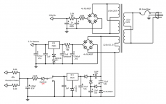
Alright, so I'm designing a tube mic pre and I've found a suitable transformer for the high voltage, but I'm left with two 6.3v taps to supply a DC regulated Filament supply and 48v phantom power supply. I have experience with designing tube amplifiers, but this is my first dive into regulated supplies.
I've looked at a bunch of forums and schematics and this design is what I came up with. It's probably close, but I'm sure there are some mistakes in here.
My main questions are, will 12.6v be enough after rectification to work in the phantom power supply? It's a 115v primary and wall voltages are really 120v bare minimum, so the secondary is probably going to show at least 13v. On the other hand, will this be too much voltage for the filament regulator?
Also, are these component figures accurate? I'd like the supply to be smooth dc, but I don't want it to be overkill either. I might be missing some components too, like I said, I'm still trying to understand voltage regulator circuits.
Attachments
That does make sense, however right now they are sharing the filament winding so it shouldn't be interfering with the audio side of things. I figured the current draw would be pretty constant from the filaments and the current rating of 2 amps on the secondary winding should be plenty to handle 4 preamp tube filaments and a phantom power circuit for two channels. I'd love to keep just one PT in this build mostly because size is limited. I guess I could separate the 6.3v windings and use one for the dc filament supply and one for the phantom power, but that would require a lot more voltage multiplying and I'm especially concerned with how reliable that would be on the filaments, since they draw quite a bit of current.
I've done some more research and it looks like the voltages should be ok for both circuits. If I was really concerned about the phantom power I could get a regulator with an especially low dropout voltage. Either way it should be fine, I think I'm missing a few capacitors in that circuit though.
The filament regulator is seeing a lot more voltage than it needs, but it should also be ok, provided I attach it to a large enough heat sink. I still need to look into that and figure out how much heat the regulator will be dissipating. Im worried about that one more because the filaments draw so much more current. I hope I don't end up with a massive heat sink...
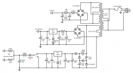
Ok I upped the voltage rating on those caps. I read somewhere that their rating only needed to be twice the input voltage, but that did seem odd to me.
I also added a few more caps and tried to fix the short. The problem was that that the voltage multiplier was already connected to ground through the bridge rectifier correct?
I also added a few more caps and tried to fix the short. The problem was that that the voltage multiplier was already connected to ground through the bridge rectifier correct?
Attachments
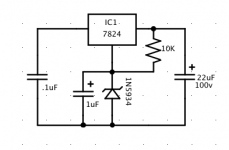
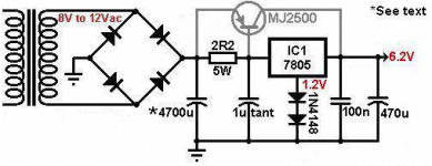
That will work if you decouple the ground pin on the regulator with a 1u cap or so and feed the pin with a 10K resistor from the supply side to stabilize the zener voltage.
Is something like this what you were referring to?
Attachments
9W is pretty high, and even if you can theoretically go away with a 11°C/W sink, I wouldn't recommend it.I calculated the filament voltage regulator's power dissipation. It shouldn't get any higher than 9w at high wall voltages. That's not terrible right? A 11C/W heatsink should be ok for that I think.
If you position your 4700µ cap after the 2.2 resistor, the overall dissipation will be somewhat reduced, and it will mainly be centered around the resistor, not the silicon.
Additionally, the peak currents will be much reduced, which is beneficial for a number of reasons.
The first line cap(s) only need a √2*V~ rating, the second line twice that, etc, unless they are chained in which case the voltage rating does not change with the orderOk I upped the voltage rating on those caps. I read somewhere that their rating only needed to be twice the input voltage, but that did seem odd to me.
That was indeed the problem, but I am not sure it is completely solved: I think the last cap of the multiplier will conflict with the input cap of the regulator (you should use denominators for the components and draw the schematic from left to right: it makes things easier when you need to communicate with other people).I also added a few more caps and tried to fix the short. The problem was that that the voltage multiplier was already connected to ground through the bridge rectifier correct?
The problem would require an in-depth analysis, but normally a diode would be needed to isolate the voltages having different AC references; it could work in the end, but a sure solution is to omit the last cap of the multiplier and rely on the last diode for the isolation.
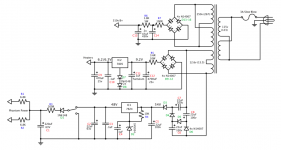
Okay, I made some modifications to the circuit based on Elvee and JonSnell's suggestions. I also added component names for easy reference. Unfortunately, there was no easy way to flip the schematic to go from left to right so I left that part alone.
I moved R5 behind C12 and also upped its value to 3.3ohms. This should drop the voltage to even safer levels, but not so low that the regulator won't function. The regulator should still have at least 2.5 volts to drop, even with a wall voltage as low as 120V. R5 will dissipate about 5 watts and IC1 will dissipate about 3.5 watts.
I also removed the capacitor right after D3 to fix grounding issues as per Elvee's suggestion. Will this however, negatively effect the performance of the voltage quadrupler or was it just meant for additional smoothing? In the latter case I guess C5 would be sufficient for this.
Finally, C4 and R4 were added to help stabilize the zener voltage.
I'm still a little worried about the grounding. I looked around online, and I found a very small torroidal transformer that would be perfect for supplying the phantom power. I would actually use a bridge rectifier instead of a voltage multiplier if i used this transformer, and it's only 10 dollars. If i did use this though it would limit space unless I could mount it close to the other power transformer (also torroidal). I know their magnetic fields are much more contained than traditional PTs, but mounting them right next to each other be a bad idea? I was thinking about mounting the phantom power PT on the side of the 2u rack enclosure (it's that small!) and then the Main PT could sit on the bottom panel right next to it.
I think at the end of the day I'd still prefer to use one PT. If this current design checks out I think that's the option I'd go with.
Attachments
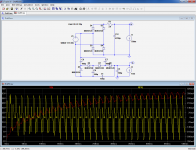
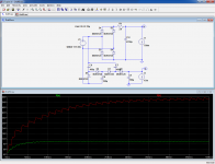
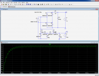
I have made a quick and rough sanity check.
The filament part is OK: the 7805 has enough room to operate, without undue dissipation.
The 48V doesn't manage to regulate with the values shown: the 22µF caps are too small, and this leads to excessive losses in the multiplier.
Things look better with 100µF throughout.
Note that with the 7824, it is prudent to respect the minimum 5mA load currents: some of them might have an uncontrolled output voltage under zero-load condition.
The 100µF remain sufficient for a 15mA load.
In order to leave no turn unstoned (or vice-versa), I have also checked the duplicate cap configuration: it confirms my gut feeling: it creates a conflict, with the output ripple having a funny look, and nasty current spikes through the two caps in question.
This means that it is wise to omit C1, as it would go with a bang rather quickly.
Note that this sim is simplified, and doesn't take into account the parasitic parameters of the transformer; in reality, voltages might somewhat differ, etc
Attachments
Wow Elvee, I really appreciate you going through the trouble. I need to get acquainted with LTspice (I believe I've already downloaded it), it seems incredibly valuable for this sort of thing.
I went ahead and changed those cap values to 100uF. I'm curious about the minimum 5mA load on the 7824 though. Some microphones (such as the Neumann U87) will draw as little as 0.8mA and many others only draw 1 or 2mA. This supply will be for two channels, but that won't matter when I'm only using one. Is there can I get around this 5mA minimum?
Also, I re-read Merlin Blencowe's web page on filament supplies (where I got the regulated DC supply circuit from), and he says that the 7805 can supply a max current of 1A. Unfortunately, my preamp will draw just over this at 1.2A. He suggests using a transistor to raise this max current to 5A, but I'm not quite sure how to arrange it now that the circuit has been somewhat rearranged. Could I add another 4700uF cap before the dropping resistor and then try to connect the transistor in the way Merlin shows? OR, can I get away without the transistor?
Again, I really appreciate all the help! ...And I'm glad I don't have to go to another transformer, seems like such a waste of iron")
I went ahead and changed those cap values to 100uF. I'm curious about the minimum 5mA load on the 7824 though. Some microphones (such as the Neumann U87) will draw as little as 0.8mA and many others only draw 1 or 2mA. This supply will be for two channels, but that won't matter when I'm only using one. Is there can I get around this 5mA minimum?
Also, I re-read Merlin Blencowe's web page on filament supplies (where I got the regulated DC supply circuit from), and he says that the 7805 can supply a max current of 1A. Unfortunately, my preamp will draw just over this at 1.2A. He suggests using a transistor to raise this max current to 5A, but I'm not quite sure how to arrange it now that the circuit has been somewhat rearranged. Could I add another 4700uF cap before the dropping resistor and then try to connect the transistor in the way Merlin shows? OR, can I get away without the transistor?
Again, I really appreciate all the help! ...And I'm glad I don't have to go to another transformer, seems like such a waste of iron
Attachments
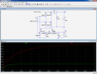
You could be lucky, or you could hand-pick one that behaves properly at zero-load, but I wouldn't recommend it: it could well misbehave if the mains voltage is a bit high, or if the ambient temperature is a bit hot, or both combined. Your safest option is to use a 10K bleeder; not very elegant, but in this case the wasted power is ridiculous (especially compared to what the tubes need)I went ahead and changed those cap values to 100uF. I'm curious about the minimum 5mA load on the 7824 though. Some microphones (such as the Neumann U87) will draw as little as 0.8mA and many others only draw 1 or 2mA. This supply will be for two channels, but that won't matter when I'm only using one. Is there can I get around this 5mA minimum?
Properly cooled, and if the input voltage is reasonable, the 78xx series can supply 1.5A. However, with cold filaments, the current drawn will be much higher, and your preamp may take a long time, if not forever for starting.Also, I re-read Merlin Blencowe's web page on filament supplies (where I got the regulated DC supply circuit from), and he says that the 7805 can supply a max current of 1A.
I would not recommend boosting regulators in this way: there are better options, like heftier types: the LM323 can provide twice the current without unpleasant tradeoffs.Unfortunately, my preamp will draw just over this at 1.2A. He suggests using a transistor to raise this max current to 5A, but I'm not quite sure how to arrange it now that the circuit has been somewhat rearranged. Could I add another 4700uF cap before the dropping resistor and then try to connect the transistor in the way Merlin shows? OR, can I get away without the transistor?
Also in the "historic" regulators, there are adjustable types, like the LM350, the LM338 or the LM396 that have higher current capabilities and can be configured for 6V.
All founders like LT now have specific types, generally with better characteristics.
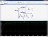
Now, there is another problem: I based my calculations on 700mA, and if you need 1.2A, the input voltage is going to be too low for a standard regulator to operate, see sim. You could be lucky, if your transformer is overdesigned, but I wouldn't bet on it: it is safer to reduce the series resistor. With 2.2Ω, it seems to just pass, but 1.8Ω is probably safer. Once again, it very much depends on the actual characteristics of your transformer. You could adjust the value once you have built the actual thing, this will avoid unnecessary heat
Attachments
Ok, bleeder resistor has been added, and the LM323 and 1.8ohm power resistor have replaced their counterparts. This is great, definitely a safe initial build, and I think I've learned enough to make any necessary adjustments after testing! Can't thank you enough, Elvee.
I wish I could more accurately predict the voltage drop in the transformer windings, but the manufacture doesn't offer the necessary information to do this. It's really not a big deal though, as you said Elvee, it's simple enough to fire it up and test the voltage.
The filament taps in series can provide 3A which will be close to max on initial startup, but then it will probably idle slightly above half that once the filaments are hot. The B+ taps in parallel can provide 400mA which is way more than I need. I guess in this regard the transformer is oversized, but it needed to be to supply the necessary voltage and current for the DC regulated filament. It's a very reasonably priced PT anyway.
If anyone is curious, this is an Antek power transformer. I've read good things about their performance and low noise on this forum. If anyone else is looking to build a tube preamp and wants to power everything from one piece of Iron, looks like the dual filament taps in the Anteks will get you there.
Attachments
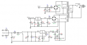
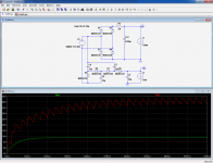
One or two final remarks: it would be better to return R4 to the output of the regulator: this will reduce the output ripple.
A similar scheme can be implemented around IC2 (with 1 or 2K): it will improve the stability.
Note that C8 only needs to be rated for 25V, C6 for 40 or 50V, and C7 for 63V.
It is unimportant, except if you have limited space.
Edit: if you make R4 4K7, it will also serve as a bleeder and you can eliminate R8 completely
Last edited:
you may need a second regulator to reduce the noise and ripple further, a single regulator may not be sufficient to provide microphone level noise free suply. an LT 3014 has a high ripple rejection. further more this type of supply easily injects noise in the ground wires, so it's not a slam duck..
- Status
- This old topic is closed. If you want to reopen this topic, contact a moderator using the "Report Post" button.
- Home
- Amplifiers
- Power Supplies
- Phantom power supply from tube power transformer