Last week I installed a couple of Tung sol 6550's in a 50 Watt Marshall guitar amp. It ran Nos Tesla EL34's before without any problem.
When driving the output stage hard (as I ALWAYS do ), I noticed some grid glowing. When measuring the voltage drop over the 1K screen grid resistors, it measured around 50 volts. That's 50 mA, or about 17.5 Watts of screen grid dissipation . B+ is around 420 V, screens a bit lower. That's within specs for the 6550's.
However, I was told that I could protect the screen grids by lowering the voltage applied on them with a regulator. That should be safer without a noticable impact on the sound of the output stage.
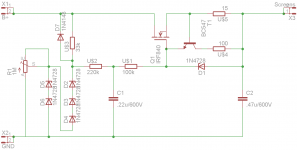
I'v come up with the following designs, which are not my own by the way. What do you think and where do you see room for improvement? R3 and R14 are 1M and 100k resp. trimpots by the way.
When driving the output stage hard (as I ALWAYS do
), I noticed some grid glowing. When measuring the voltage drop over the 1K screen grid resistors, it measured around 50 volts. That's 50 mA, or about 17.5 Watts of screen grid dissipation . B+ is around 420 V, screens a bit lower. That's within specs for the 6550's. However, I was told that I could protect the screen grids by lowering the voltage applied on them with a regulator. That should be safer without a noticable impact on the sound of the output stage.
I'v come up with the following designs, which are not my own by the way. What do you think and where do you see room for improvement? R3 and R14 are 1M and 100k resp. trimpots by the way.
Attachments
Thanks RTF671. It's a 50 Watt non master volume Marshall, modded to the specs of one of Slash's amps (SIR #34). The output is conventional Marshall, just with 6550's instead of EL34's.
It sounds wonderous. With EL34's it had loads of compression and mids. 6550's gave it lows and much cleaner, less compressed mids. It still has that great bite Marshalls are famous for. It sounds an awfull lot like Use your illusion from GnR...
I'd like to retain that thightness and the lack of compression.
I included a schematic of a Marshall with 6550 tubes. Same output stage as in my amp.
Attachments
Right now, the easiest solution is to increase the screen grid stopper. Sub out your 1k for a 5k6. That will lower the screen voltage quite a lot. Also that should increase your compression. During loud passages the screens will attempt to draw more current which will cause the voltage to drop. A screen voltage that is much lower than your plate will cause that compression. Regulation is possible but is definitely a bag of it's own tricks (and not recommended; it's complex with limited benefits).
Do you plan on going back and forth between tubes often?
Do you plan on going back and forth between tubes often?
I don't plan on switching tubes very often as it would incorporate adjusting the bias circuit too. Not an awfull lot of work, but like I said: I love the raw power of the 6550's. Just more hard rock to my ears than EL34's.
I will use 5K screen grid resistors. 5Watt is probably fine right?
Can you elaborate please about the 'bag of tricks' when going the regulator route?
I will use 5K screen grid resistors. 5Watt is probably fine right?
Can you elaborate please about the 'bag of tricks' when going the regulator route?
I don't plan on switching tubes very often as it would incorporate adjusting the bias circuit too. Not an awfull lot of work, but like I said: I love the raw power of the 6550's. Just more hard rock to my ears than EL34's.
I will use 5K screen grid resistors. 5Watt is probably fine right?
Can you elaborate please about the 'bag of tricks' when going the regulator route?
Best to use a 20W rating, or I'll bet you'll be repairing it again.
You can use 5W resistors but use four 1.5k 5W in series or four 20k 5W in parallel. Regulators would require transistors or zeners (possibly several), they would need heat sinks, other passive components, a board (bread/PCB) to house the whole thing. It's quite a commitment.
Those are the practical considerations. The zeners in the design I posted can be low wattage. The Mosfet can use the amp chassis as a heatsink and I can always mount a heatsink in the chassis or on top of it. Yeah, I'm quite committed to my amps and their well being.
Are there other trade offs when regulating?
Are there other trade offs when regulating?
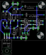
Made a schematic and a board. Please have a look and feel free to suggest improvements/changes to the design of the regulator and board. I'm just making educated guesses as I'm a novice with discrete technology...
Have to make my apologies for not making clear enough that I was trying to figure out how/if the regulator would work in the first place. I knew larger resistors would mean more compression. A solution I was therefor trying to avoid.
Have to make my apologies for not making clear enough that I was trying to figure out how/if the regulator would work in the first place. I knew larger resistors would mean more compression. A solution I was therefor trying to avoid.
Attachments
Last edited:
I'm not much of a designer when it comes to electrics. But I solve problems and know what to tweak to get the sound I want. When it comes to guitar pre amps that is. Regulating voltages this way is new to me. But I'm always eager to learn a new 'trick'.
Output varies with the turn of a trimmer from 421 to 291 Volts. Thats before the usual screen grid resistor and loaded with 10 mA. I simulated with a steady load. Varying the load makes no difference (of course), until I get to 40mA. Then the current becomes limited.
Now the next question: where do I set the screen voltage? What is good practice?
I'm not so great with solid states but valves I know a bit about. So, pentodes operation is a mixture of the voltages on the plate and the screen as well as the bias. You could set the screen voltage to almost anything to have it perform like you want. Since you want compression we'll have it a bit lower with a chunky screen stopper to add it.
Before you start with regulation though, I'd suggest taking a look at the bias. Screens drawing too much current typically come from hot bias. With a few tweaks (which could accommodate more than one type of tube) to things we could avoid the regulator and still have the amp operating normally.
Other than the 6550s and the #34 is anything else different on the amp? Also do you know what voltage the PT puts out? With those numbers I could draw up a diagram and show you what the performance will look like.
The amp is in the studio right now, but I will take it home tonight after practice so I can take more measurements.
One thing I'm sure about is that I biases like the amp runs EL34's. I usually bias for 0.7*25(W)/B+ (17.5/430=40mA). That is really low for 6550's, but was advised to do so because biasing hotter could (!) put stress on the PT. I noticed the same glow when biasing hotter by the way. The PT stayed luke warm even when on 60mA per tube (which is a lot closer to the plate dissipation on 6550's).
Tubes are brand spankin' new Tung Sols. I guess they are not the most robust tubes around...
And to be clear about it: I like the uncompressed sounds of 6550's compared to EL34's. I'd like them to stay uncompressed if possible.
Other changes are:
- less NFB (100k from 8 Ohm tap; see schematic. That was fine wih EL34's);
- tail resistor in LTP up to 22k from 10k (less drive!);
- numerous tweaks in the preamp, but thats the not affecting the power amp.
This weekend I'm of to the shop to buy larger screen grid resistors.
One thing I'm sure about is that I biases like the amp runs EL34's. I usually bias for 0.7*25(W)/B+ (17.5/430=40mA). That is really low for 6550's, but was advised to do so because biasing hotter could (!) put stress on the PT. I noticed the same glow when biasing hotter by the way. The PT stayed luke warm even when on 60mA per tube (which is a lot closer to the plate dissipation on 6550's).
Tubes are brand spankin' new Tung Sols. I guess they are not the most robust tubes around
... And to be clear about it: I like the uncompressed sounds of 6550's compared to EL34's. I'd like them to stay uncompressed if possible.
Other changes are:
- less NFB (100k from 8 Ohm tap; see schematic. That was fine wih EL34's);
- tail resistor in LTP up to 22k from 10k (less drive!);
- numerous tweaks in the preamp, but thats the not affecting the power amp.
This weekend I'm of to the shop to buy larger screen grid resistors.
- Status
- This old topic is closed. If you want to reopen this topic, contact a moderator using the "Report Post" button.
- Home
- Amplifiers
- Power Supplies
- Screen grid voltage regulator