Hi,
I've built my very first power amp (a 8W class A single rail amplifier based on a Juma design). The PSU and amp boards have been tested working, and the final task left is to put them into a case.
However, despite reading a lot in this forum, I'm not very sure of what should be the proper way to do so - and terms like ground loop, chassis ground, power ground, signal ground, audio ground, ground bus, star ground ... are confusing (to me) as ever. Worse yet, some gurus seem to disagree on certain topics.
Therefore, I drafted the attached diagram showing how I plan to install the wiring in the case, and I would like helps in pointing out mistakes I've made, as well as any comments.
Thanks for your help in advance.
Attachments
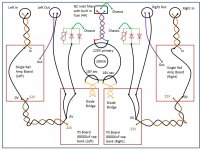
The inputs, the LV AC and the mains are correct.
Do you have a single polarity power supply? to a single polarity amp?
The outputs are wrong.
The return from the output should be close coupled to the Flow all the way back to the source of the current.
You have taken the return as close coupled back to near the amp pcb and then put in a BIG LOOP to the PSU !!!!!
Thanks Andrew for your comments.
So far they work OK on the bench, but I noticed that when the wiring were too messy, oscillation could occur.
Thanks, will correct that.
I was worrying about inrush current due to the large cap bank (176mF in total), hence used a bigger fuse. Would inrush current be an issue?
Does the assembly work properly on the bench?
So far they work OK on the bench, but I noticed that when the wiring were too messy, oscillation could occur.
The outputs are wrong.
The return from the output should be close coupled to the Flow all the way back to the source of the current.
You have taken the return as close coupled back to near the amp pcb and then put in a BIG LOOP to the PSU !!!!!
Thanks, will correct that.
Why did you use a 4A filter for a 200VA transformer?
200VA / 230Vac needs ~ 900mA fuse and ~ 900mA filter.
Use a T800mA fuse and use a 1A filter.
I was worrying about inrush current due to the large cap bank (176mF in total), hence used a bigger fuse. Would inrush current be an issue?
Do you have a single polarity power supply? to a single polarity amp?
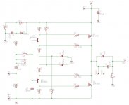
Yes, it's a single polarity power supply to a single polarity amp. Attached is the schematic of the amp. (just that 24V became 22V due to the transformer I received).
Attachments
A soft start limits the transformer start up current.
Big capacitance is not usually a problem.
Add a soft start and try a T1A fuse to see if it allows more than one restart after depleting the cap bank.
If the cap bank does blow a T1A fuse with the soft start fitted then look at adding a slow charge circuit. A bypassed Power Thermistor in the transformer secondary/ies
if you get oscillation or evidence of instability when wires are moved around then your WIRING is at fault. Either excessive radiating of interference or excessive pick up of interference.So far they work OK on the bench, but I noticed that when the wiring were too messy, oscillation could occur.
Correct the wiring.
I wrote in another Thread a few minutes ago:
This applies to every wire pair in the amplifier, speakers, PSU, low level signal, feedback (traces), every PAIR!EVERY SIGNAL connection is a TWO WIRE connection.
The Source supplies the current to the Flow wire of the pair. The Source receives back the Return current through the other wire of the PAIR.
The CURRENT that leaves the Source MUST come Back to the Source, exactly.
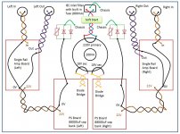
That looks good.
Wire that up on the bench and prove it works first for a mono assembly, then for the other mono assembly and finally for a stereo assembly.
Move all the pairs around. Prove that there are no interference effects. fold the assembly into roughly the shape and locations that will fit in the chassis. this should still work.
When that has been proved, move the whole assembly to the chassis, exactly duplicating each electrical connection.
They provide a high current route from All the Audio Grounds to the Chassis.
The Chassis is connected to Protective Earth.
This is what prevents the input terminal killing you, if there is ever a fault that takes the Mains live to touch some other internal part.
BUT !!!!!
the route through the "ground loop breakers" MUST be designed to pass kA and survive long enough for the Fault Current to blow the mains fuse and for the arc to extinguish.
That is an onerous task !!!!!!
...the route through the "ground loop breakers" MUST be designed to pass kA and survive long enough for the Fault Current to blow the mains fuse and for the arc to extinguish...
I plan to use a Vishay 35A/1200V diode bridge (VS-GBPC3512A), plus a CL-60 in parallel to be the ground loop breaker.
http://www.vishay.com/docs/93575/vs-gbpc25.pdf
Would that be OK?
I have used both a 25A and a 35A bridge rectifier for the Disconnecting Network.
I can't remember which I tested.
I did use the parallel diode arrangement, not the series diode arrangement.
Parallel diode arrangement requires two shorting links:
one across ~~ and another across +-
Two adjacent tabs become the Chassis and MAG connections.
I use a low power resistor and a low value capacitor across any two adjacent tabs.
A CL60 is a waste of money in this duty. Save it for what it is designed for: slow charging of capacitance.
A pair of parallel diodes each rated at 35A will give an effective 700A diode for single pulse duty when the pulse duration is short.
If the pulse duty is very short I would expect the 35A diodes to go way past 1400Apk.
Last edited:
The schematic in post #6 doesn't appear to contain any frequency compensation inside the NFB loop. None at all! Since the topology consists of a pair of Common Emitter amplifiers driving a pair of Common Source amplifiers, it's got plenty of opportunities to accumulate unwanted phase shifts, and become marginally stable or even unstable. This could lead to oscillation. It's noteworthy, and frightening, that you've observed oscillation in testing.
I'd recommend you consider hiring someone to model the amplifier in SPICE simulation, and have them extract phase margin & gain margin from AC analysis. These will help you determine whether it's necessary to add explicit frequency compensation components, or not.
I'd recommend you consider hiring someone to model the amplifier in SPICE simulation, and have them extract phase margin & gain margin from AC analysis. These will help you determine whether it's necessary to add explicit frequency compensation components, or not.
Hi Mark,
Thanks for your comments, the original designer did include provisions for capacitors across the feedback resistors, and can be used to deal with oscillations in case necessary, but the builds made so far are stable without the frequency compensation, so I have not included the caps into my build, but your points are well taken and I'll give it a thought. BTW, in my bench setup, none of the cables were twisted, and I observed oscillation when the input and output wires were closely parallelled with each other, while driving the amp to almost clipping with a 20kHz sine wave, so I'll blame my wiring for that (for now).
As for SPICE, I'll learn to use it, but I've spent 2 months and still mid-way through Bob Cordell's book, and it'll take some time before I can reach the chapters for SPICE (after Bob's book will be Douglas', DIY is not easy ).
Thanks and regards.
Last edited:
- Status
- This old topic is closed. If you want to reopen this topic, contact a moderator using the "Report Post" button.
- Home
- Amplifiers
- Power Supplies
- Encasing my first power amp