Did you misinterpret my transformer winding data? For column 5 you are showing 26 turns. My primary is split with bias and secondary windings between primary windings. I have a total of 52 turns which is what the PI tool calculated.all in all I assume you need about twice the primary turns for 65kHz operating frequency
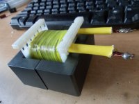
I have had the power supply running for 1 hour now under a 1.17 amp load (according to my meter). With my temperature probe sandwiched between the core and coil, I am reading 55 degrees C.
This is a prototype I was making for test purposes. I have some #28 wire on order and will wind a transformer with 2 strands of that for the primary which should reduce core temperature rise. I will also use 2 strands of #30 for the secondary winding. I don't won't to deal with the problems associated with trying to obtain litz wire.
The actual application I will use this in is a 15 watt LM1875 amplifier. It will be used for a background music application. So 99% of the time the current draw will be in the 2-300 ma range (60 ma of that will be the LM1875 idle current). If a voice announcement is made, it will probably peak slightly over 1 amp. The application will be a field test to compare the switching power supply to an older 60 Hz design.
obviously I misinterpreted your winding data.
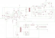
Meanwhile I built an spreadsheet for discontiuous mode that I played with a little.
Doing so i found flyback voltage of 70V should be fine for US-mains.
Beyond this I agree with you that load performance seems quite healthy
Meanwhile I built an spreadsheet for discontiuous mode that I played with a little.
Doing so i found flyback voltage of 70V should be fine for US-mains.
Beyond this I agree with you that load performance seems quite healthy
Attachments
Last edited:
Voltwide, thanks for confirming the design is acceptable. I will continue to run additional tests once I have the #28 wire in and can wind a second transformer. I will add the additional 2 turns to the primary that your new spread sheet shows. Thanks for taking the time to create it.
As for safety requirements, if this design ends up in production, the transformer will be made by a tranformer supply house. They will have to meet all safety requirements.
As for safety requirements, if this design ends up in production, the transformer will be made by a tranformer supply house. They will have to meet all safety requirements.
Rcbuck, designing the ultimate flyback transformer is indeed a big deal. For instance the power dissipated in the primary snubber resistor can be greately reduced by interleaved windings, i.e. a split primary winding enclosing the secondary in between. I found this technique common in notebook adapters rated 50W and more.
The snubber resistors I found were 2 or 3 smd parts, and it works!")
The snubber resistors I found were 2 or 3 smd parts, and it works!
Can this kind of supplys also give plus and minus 110 volts 100mA, 6.3 volts 3 amps, and plus minus 65 volts 15 amps.?
for a hybrid amplier who I have design it working now on a normal transformer but copper get expensive these days and a smps is a solution for that.
I think aI need a siemens big core for that (windings fit).
regards
kees
for a hybrid amplier who I have design it working now on a normal transformer but copper get expensive these days and a smps is a solution for that.
I think aI need a siemens big core for that (windings fit).
regards
kees
rcbuck, it's easy to think that a manufacturer can make your prototype safety compliant, but unless you make the prototype pretty close to the required end result you may find the final performance very different, or a final design impossible due to lack of winding room. Preferably try and make up some margin tape and design your prototype for the reduced winding width per layer.
The snubber layout and part selection is as important as the primary and secondary side switching loops, which is where a surface mount pcb and smt parts really are your friend. Doing any prototype in leaded parts is fraught with risk unless you take a lot of care and attention.
The snubber layout and part selection is as important as the primary and secondary side switching loops, which is where a surface mount pcb and smt parts really are your friend. Doing any prototype in leaded parts is fraught with risk unless you take a lot of care and attention.
Can this kind of supplys also give plus and minus 110 volts 100mA, 6.3 volts 3 amps, and plus minus 65 volts 15 amps.?
for a hybrid amplier who I have design it working now on a normal transformer but copper get expensive these days and a smps is a solution for that.
I think aI need a siemens big core for that (windings fit).
regards
kees
Definitely not. For high power, the flyback is the worst topology of all. Winding losses, snubber losses, rectifier losses, current ripple will be enormous.
Definitely not. For high power, the flyback is the worst topology of all. Winding losses, snubber losses, rectifier losses, current ripple will be enormous.
I do mean, a smps in general, so for high power a half bridge, or full brigde, so real power smps types.
So maybe the question is a little out of topic for this threat.
regards
kees
Assuming 1V diode voltage drop bridge rectification losses sum up to 300W.
Wel there are inverters for welding exceeds 150 ampere.
just with diodes like these in schematic. 150EBU02
But are current souce supplys and I need constand voltage, so a voltage feedback put in
do this for me, and the current feedback just as a protection for to high current, then I have
a ordinairy constant voltage source in my eyes?
regards
kees
Attachments
Last edited:
Ohh this excists
thanks
wel I can not join I have ask it because this is needed.
Last edited:
- Status
- This old topic is closed. If you want to reopen this topic, contact a moderator using the "Report Post" button.
- Home
- Amplifiers
- Power Supplies
- Best Flyback Design Tool?