Hi all,
I need a power supply for about 6 op amps. I've searched, but most online resources have a center tapped AC, then rectifier, then a 78xx/79xx pair to create +Vcc and -Vcc with virtual ground. All in all it's been a great learning experience, but I keep banging my head against a few conceptual issues.
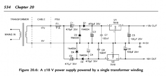
I have a nice spare laptop power supply that gives me clean +18 VDC. Douglas Self's book gives the attached solution for a split rail power supply off an AC wall wart - could I substitute my handy dandy laptop power brick where it says "cable" and forgo the diodes in Self's schematic?
Or is there an easier solution to get +/- 15VDC off a 18VDC laptop power supply? Using a voltage divider would give me +9/0/-9, which is not enough.
Then again, because voltage is relative, why wouldn't I just be able to put 18V and 0V DC straight to the op amps? If I understand correctly, the op amp won't care if it's [-9 and +9], [0 and 18] or [100000 and 100018] for that matter. Right?
Thanks a lot")
I need a power supply for about 6 op amps. I've searched, but most online resources have a center tapped AC, then rectifier, then a 78xx/79xx pair to create +Vcc and -Vcc with virtual ground. All in all it's been a great learning experience, but I keep banging my head against a few conceptual issues.
I have a nice spare laptop power supply that gives me clean +18 VDC. Douglas Self's book gives the attached solution for a split rail power supply off an AC wall wart - could I substitute my handy dandy laptop power brick where it says "cable" and forgo the diodes in Self's schematic?
Or is there an easier solution to get +/- 15VDC off a 18VDC laptop power supply? Using a voltage divider would give me +9/0/-9, which is not enough.
Then again, because voltage is relative, why wouldn't I just be able to put 18V and 0V DC straight to the op amps? If I understand correctly, the op amp won't care if it's [-9 and +9], [0 and 18] or [100000 and 100018] for that matter. Right?
Thanks a lot
Attachments
You have choices.
a.)
use the single polarity SMPS and create a "virtual ground" using an active circuit that has low impedance. This creates an effective +ve, zero volts and -ve supply for the opamp circuits
b.)
use the single polarity SMPS and convert the opamp circuit to use a single polarity supply.
BUT !!!!!
the ripple coming from the SMPS will be horrendous. Battery charging with a noisy SMPS does not care about the noise. The opamps working with analogue audio signals will care a lot.
You will need to use an RCRC filter between the DC output of the SMPS and the regulators. That combination should get the noise low enough that the opamps behave and process your audio signals.
If your opamps can't work with ~12Vdc (or +-6Vdc), then your SMPS is not going to work.
c.)
buy a transformer with dual secondary windings, the correct voltage and adequate VA.
Last edited:
That design from Self is great. Simple, with a real ground return but relies on the input being AC. The output of your supply is DC and if you hook it up the way you suggest you'll get good voltage (not saying clean) on your positive supply, but nothing on the negative. Like Andrew said, you'll need a virtual ground to use a single ended DC supply. The designer or the O2 headphone amplifier had a great page on virtual grounds, I recommend reading it to decide if that's the way you'd like to go: NwAvGuy: Virtual Grounds & 3 Channel Amps
Otherwise, to use the Self power supply you'll need to get the transformer he suggests. It would be much cleaner since filtering switching noise can be difficult.
Otherwise, to use the Self power supply you'll need to get the transformer he suggests. It would be much cleaner since filtering switching noise can be difficult.
Short answer is no. Period.
If you want to use Self´s circuit you´ll need the transformer he specifies, but given that, just get the proper center tapped transformer and build a conventional supply.
Pity your circuit will not work with +/-9V ... which in fact will be even less, because you need to clean/filter them.
If you want to use Self´s circuit you´ll need the transformer he specifies, but given that, just get the proper center tapped transformer and build a conventional supply.
Pity your circuit will not work with +/-9V ... which in fact will be even less, because you need to clean/filter them.
That said, you can use one of the popular charge pump ICs which provide an easy and cheap solution to getteing negative rails.
The classic TC7662 straight converts +15V to -15V .
http://ww1.microchip.com/downloads/en/DeviceDoc/21469a.pdf
If you want to get sophisticated, the LTC3260 does the same, plus gives you regulated and very clean +12V and -12V
http://www.linear.com/docs/41410
Armed with the chip numbers, search the web, somebody must have posted a practical project including some PCB ... or design your own
Why cant he just use 0-18v as it is? Personally i would build the cirucit above with linear regulators and pickup a transformer cheap on eBay.
If I understand all answers correctly (well, I hope so anyway!) then 0-18V would give me insufficient headroom (same as using +9V and -9V) and the output will be terribly noisy since the DC laptop brick I have it probably poorly regulated as the laptop brick is designed to dump raw power into a battery.
Thanks everyone for the suggestions. The single chip solutions like TC7662 will probably not give me enough power for at least 6 opamps, and I was hoping I could do without a transformer (weight is an issue), but it does seem like the cleanest/most straightforward option at the moment. Although the active virtual ground looks good, too, be it a little more complicated conceptually (thus, prone to dumb errors from my part, haha!)
You could use a 12 to -/+ 15 volts dc convertor. Simply regulate the laptop supply down to 12 with a 7812 and use that 12 volt feed for one of these. They come in all varieties and power outputs. Choose your opamps carefully and a 2 watt convertor may be sufficient.
This is just an example.
IH1215S - XP POWER - CONVERTER, DC/DC, 2W, +/-15V | Farnell UK
This is just an example.
IH1215S - XP POWER - CONVERTER, DC/DC, 2W, +/-15V | Farnell UK
You could use a 12 to -/+ 15 volts dc convertor. Simply regulate the laptop supply down to 12 with a 7812 and use that 12 volt feed for one of these. They come in all varieties and power outputs. Choose your opamps carefully and a 2 watt convertor may be sufficient.
This is just an example.
IH1215S - XP POWER - CONVERTER, DC/DC, 2W, +/-15V | Farnell UK
Thanks again! I should be calling the project "The Mooly" by now, haha.
Your IC solution is exactly what I was looking for (although I had searched I wasn't sure where to start and couldn't see the forest for the trees). I guess a 3 watt should be plenty for 6 tl072s.
Some links on virtual grounds...
http://www.diyaudio.com/forums/power-supplies/174791-virtual-ground-power-amp-applications.html
Virtual Ground Circuits
I never built used the above circuit, but I did test it out and everything worked well enough...
http://www.diyaudio.com/forums/power-supplies/174791-virtual-ground-power-amp-applications.html
Virtual Ground Circuits
I never built used the above circuit, but I did test it out and everything worked well enough...
Your 6 x TL072 (12 individual Op Amps) need 3 mA each or a total of 18 mA.The single chip solutions like TC7662 will probably not give me enough power for at least 6 opamps
A single 7662 converter when supplying 18mA has an internal resistance of 50 ohms, for a 0.9V loss, so it will turn raw +18V into -17V .
You can turn both into very clean +/-12V with a pair of 78L12/79L12 for a simple, cheap and compact solution
Much better than very dirty +18V by the way
FWIW I make (among other things) portable guitar, bass and PA amplifiers , fed from a 12V7AH battery for reasonable weight.
I need a negative rail for the preamp TL072 , and I have been making them from the Stone Age on, no fancy pump converters way back then, so I designed my own with available everywhere NE555 .
I get between -9V and -10V (depending on load), plus original +12V to feed my TL072 which are happy with them.
They do not need perfect symmetrical supplies by the way ,)
Here´s the smallest one, 30W biamplified (20+10W RMS, 10" speaker + LeSon tweeter)


4 x TL072 in total, fed from a non dedicated cheap IC, how´s that?
hvergelmir, where are you located? I have some very nice dc-dc converters and would be willing to let one go for only the shipping cost. This is the converter...
BWR-15/330-D12A-C Murata Power Solutions | Mouser
I've used these to power many op-amp projects.
BWR-15/330-D12A-C Murata Power Solutions | Mouser
I've used these to power many op-amp projects.
hvergelmir, where are you located? I have some very nice dc-dc converters and would be willing to let one go for only the shipping cost. This is the converter...
BWR-15/330-D12A-C Murata Power Solutions | Mouser
I've used these to power many op-amp projects.
I'm in the Netherlands, so if you're stateside then I'm not sure if it's feasible - although I really do appreciate your generous offer
Do the TL072s really draw so little current? I've seen wildly differing figures on the internet - from 2 to 50mA per chip...
BTW, your portable amps look pretty cool JMFahey!
Quiescent current.
You need to add on output current.
and not just for the resistive loads, but for the capacitive (inadvertent) loads and for the feedback loads.
Allow a peak current of half the short circuit current.
That would be ~20mA per opamp channel.
Design for 120mApk
You need to add on output current.
and not just for the resistive loads, but for the capacitive (inadvertent) loads and for the feedback loads.
Allow a peak current of half the short circuit current.
That would be ~20mA per opamp channel.
Design for 120mApk
I'm going to disagree with Andrew on this. Practicalities... I still have my 7 opamp D Self test PCB, and this is a low impedance version that uses 4k7 pots for bass, 2k2 for treble, 1k for treble turnover and 4k7 for bass turnover. So its not really suitable for TL072's because its asking to much to drive it fully... however...
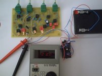
Here it is fitted with TL072's and fed from a 12 to 15/15 convertor with 1 ohm resistors in the supply to determine current draw. This uses 7 opamps.
Current draw quiescent was 23.1 ma
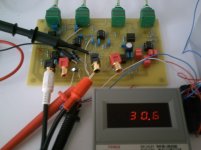
Current draw at 16 volts pk/pk output at 1kHz was 30.6 ma
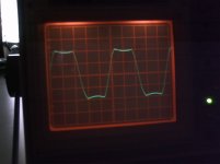
Current draw at 10 kHz and max treble boost purposely driven into severe clipping was 45 ma The scale on the scope for this was 5 volts/div.
For any normal music input and with levels around a couple of volts the change in current draw from quiescent is minimal.
The small convertors that are rated around 66ma per rail will easily power 6 TL072's under signal conditions.
Attachments
I'm in the Netherlands, so if you're stateside then I'm not sure if it's feasible - although I really do appreciate your generous offer.
No problem really; 7USD shipping and it would take about a week. PM me if you're interested.
I still have my 7 opamp D Self test PCB, and this is a low impedance version that uses 4k7 pots for bass, 2k2 for treble, 1k for treble turnover and 4k7 for bass turnover. So its not really suitable for TL072's because its asking to much to drive it fully... however...
Here it is fitted with TL072's and fed from a 12 to 15/15 convertor with 1 ohm resistors in the supply to determine current draw. This uses 7 opamps.
Current draw quiescent was 23.1 ma
Current draw at 16 volts pk/pk output at 1kHz was 30.6 ma
Current draw at 10 kHz and max treble boost purposely driven into severe clipping was 45 ma The scale on the scope for this was 5 volts/div.
For any normal music input and with levels around a couple of volts the change in current draw from quiescent is minimal.
The small convertors that are rated around 66ma per rail will easily power 6 TL072's under signal conditions.
Thanks again for the extensive info. The project will be dealing with just transients, but even that should be easily within the limits. TheAnonymous, I'm going to take you up on your offer! PM forthcoming.
The solution of your problem depends upon the rating of Your op-amp. If the op-amp has the Vcc voltage range minimum 9V or less than it and maximum 18V or more than it then there is not any problem of using the 9V or 18V. But if the rating is different then you must have to design a new power supply which you can easily obtain from the existing power supply using the 78XX series regulators.
- Status
- This old topic is closed. If you want to reopen this topic, contact a moderator using the "Report Post" button.
- Home
- Amplifiers
- Power Supplies
- Split-rail DC from DC laptop power supply?