I am kindly asking for advice in determining the optimal capacitor size after the power supply regulator.
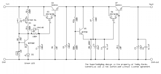
I have built a 12V 2A external power supply based on Superteddyreg. Before the regulator, I have 2 x 6800uF bypassed with 0,1uF ceramic + 22nF film capacitor so this side of the regulator is well fed. At the output of the regulator there is 10uF capacitor bypassed with 0,1uF ceramic capacitor (part of Superteddy design). The power supply connects to DAC via a 1m unshielded cable. As an additional info, Superteddyreg has no VFB or CFB, so it is essentially a voltage follower.
My questions are:
1. Should I put additional capacitor, or a bank of capacitors, after the regulator and, if yes, what would be the appropriate size in this configuration?
2. Also, if 1. is yes, should the additional caps and bypassing be put inside DAC, rather than 1m away from it?
3. Finally, does each 6800uF capacitor before regulator requires bypassing, or is one pair of 0,1uF+22nF enough for both as they are connected in parallel?
Thank you in advance.
Last edited:
I am kindly asking for advice in determining the optimal capacitor size after the power supply regulator.
I have built a 12V 2A external power supply based on Superteddyreg. Before the regulator, I have 2 x 6800uF bypassed with 0,1uF ceramic + 22nF film capacitor so this side of the regulator is well fed. At the output of the regulator there is 10uF capacitor bypassed with 0,1uF ceramic capacitor (part of Superteddy design). The power supply connects to DAC via a 1m unshielded cable.
My questions are:
1. Should I put additional capacitor, or a bank of capacitors, after the regulator and, if yes, what would be the appropriate size in this configuration?
2. Also, if 1. is yes, should the additional caps and bypassing be put inside DAC, rather than 1m away from it?
As an additional info, Superteddyreg has no VFB or CFB, so it is essentially a voltage follower.
3. Finally, does each 6800uF capacitor before regulator requires bypassing, or is one pair of 0,1uF+22nF enough for both as they are connected in parallel?
Thank you in advance.
Not familiar with the superteddy, and the required capacitance would depend on the output impedance of the reg. Do you have a schematic?
Anyway, additional capacitance is most effective where you want the clean supply - and that's as close to the DAC cicuitry as you can get it.
Personally I don't see any need for bypassing before the reg, although before long you will get lots of posts of people telling you that a xyz bypass before the reg opens up the sound stage soooo wide
")
Jan
Look at the decoupling fitted on any modern digital PCB.
There are dozens of small electrolytics and just as many smd X7R
In addition there are snubbers (R+C) on every PSU.
It's the decoupling that is important when signals change currents quickly. (the bits turning off and on in ns, or maybe ps, in very fast stages).
The PSU is usually too far away to significantly influence the fast transients.
AndrewT, thank you for your response. At this stage I wouldn't tamper with decoupling inside DAC and would like to focus on power supply delivering clean DC. Superteddyreg is already very quiet, all I need is to figure out the size and the placement of capacitors after the regulator, having in mind that there is already 10uF at the regulator output, that the designed current draw is 2A and that the DAC unit is 1m away from the external PSU. Thanks again.
But there is also the high output impedance of the power supply in play. Should I then omit any large cap at the output of regulator, take the regulated DC straight via umbilical cord to DAC and place a cap there? If so, which value would you suggest? Sorry if I keep reiterating questions.
As Andrew implied, extra cap after the reg doesn't do much for a DAC, especially with 1 meter (gasp!) of umbilical.
I assume that the 10uF there is for stability (yes emitter followers can also oscillate), so that's taken care of.
Jan
Very important note. You should also not use too much capacitance because of this, you can damp the circuit too. Emitter followers have a range of acceptable capacitance on the output that is usually quite narrow. OP, are you getting a lot of ripple or voltage sag under load?
But there is also the high output impedance of the power supply in play. Should I then omit any large cap at the output of regulator, take the regulated DC straight via umbilical cord to DAC and place a cap there? If so, which value would you suggest? Sorry if I keep reiterating questions.
Do you have any figures for that Zout?
Jan
Very important note. You should also not use too much capacitance because of this, you can damp the circuit too. Emitter followers have a range of acceptable capacitance on the output that is usually quite narrow. OP, are you getting a lot of ripple or voltage sag under load?
The system cannot be too damped - an ideal DC source (and that is what you'd want) can be said to have infinite damping. Maybe you mean the 'Q' of the capacitor with wiring L?
Jan
Do you have any figures for that Zout?
Jan
Nope, just words form the author!
Lets put some numbers on it. Lets assume the Zout is 1 ohms, and you want to cut that to 0.1 ohms at 20Hz (it automagically improves at higher frequencies).
A cap with 0.1 ohms at 20Hz is C = 1/(2*pi*f*R) = about 83,000uF.
This clearly shows the folly of trying to improve a reg with massive capacitance.
It still would not help for the high-speed pulses in the DAC because 1) such massive caps have relatively large inductance, and 2) there's still the inductance of a meter wire between the caps and DAC.
So, the no-brainer is a few good caps in the DAC. What you can do, if that is not already done, put some good film caps of say 1uF across the 470uF electrolytics which are already there.
Jan
I eliminated the capacitors after the regulator in power supply, but now I don't have dynamics. This could be due to allegedly high output impedance of Superteddyreg. I believe that next thing to try is to increase capacity at the DAC power input. Any other suggestions? Thanks to everybody.
I eliminated the capacitors after the regulator in power supply, but now I don't have dynamics. This could be due to allegedly high output impedance of Superteddyreg. I believe that next thing to try is to increase capacity at the DAC power input. Any other suggestions? Thanks to everybody.
I'd reinstall the regulator's output capacitor, since the regulator was tuned for that termination.
It's best to have the regulator as close as possible to the circuit that it powers, inside the box if possible.
The raw DC can still be external.
Last edited:
I did not remove C5 and C6 which are part of the regulator circuit, but rather the 6800uF smoothing capacitor after STR. Removing it stole the dynamics, so the sound has something to do with additional capacitors.
I know it would be ideal to have the regulator inside the box, however that is not an option because the DAC in question is MF V-DACII so it would hardy fit inside, and I would also like to keep the DAC as original as possible.
I know it would be ideal to have the regulator inside the box, however that is not an option because the DAC in question is MF V-DACII so it would hardy fit inside, and I would also like to keep the DAC as original as possible.
I did not remove C5 and C6 which are part of the regulator circuit, but rather the 6800uF smoothing capacitor after STR. Removing it stole the dynamics, so the sound has something to do with additional capacitors.
I know it would be ideal to have the regulator inside the box, however that is not an option because the DAC in question is MF V-DACII so it would hardy fit inside, and I would also like to keep the DAC as original as possible.
Looks like the external supply enters and then passes though a regulator and is shunted by a bunch of surface mount electrolytics.
Not much you can do internally easily.
I'd still shorten the cable if possible. The regulator is designed like a wide band amplifier, for good transient response,
hence the small 10uF ouput capacitor. But, the cable affects the performance.
Rayma, thanks for your response. You are right, the external DC enters the DAC at 2 x 470uF electrolytics (obviously SMT because the entire PCB is in that technology) and an internal regulator after. I still have to figure out why are the dynamics gone after removing the 6800uF output capacitor. Teddy Pardo says that no smoothing capacitors are required after the reg, however, I see people putting additional caps anyway. The only explanation I see is the already mentioned high output impedance of the circuit. But as Jan's calculation shows, an output cap would reduce it just slightly, which means that the output cap may compensate for cable length in transient response. But then again, the 1000uF at DAC input would be just enough for the same purpose in my experience.
jan.didden said:Do you have any figures for that Zout?
You have all the figures in your own webpage
http://www.linearaudio.net/images/letters.pdf/V4%20JW%20F8.pdf
- Status
- This old topic is closed. If you want to reopen this topic, contact a moderator using the "Report Post" button.
- Home
- Amplifiers
- Power Supplies
- Capacitor size after zero-feedback PS