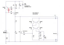
I am using a Reflektor-D, built from a Tea-Bag supplied kit, to power my Twisted Pear Buffalo 3SE board.
I plan to upgrade the DAC to TP's new ESS9028 based Buffalo board but it demands more current from its power supply, specified as 750mA. In my build I will only need about 720mA (because I don't use the Buffalo's onboard oscillator) but this is still well beyond the Reflektor-D's capability. Is it possible to modify the Reflektor D to deliver this level of current?
Thanks
The Ref-D's current ability is a matter of sinking mostly. The spec limit is for the certain on board sinks. Its a conservative current spec not a break down spec though. If you have the bare minimum Mini version for example, which is externally sinkable only, you can readily bolt it to larger sinking. If you got the full version with the onboard rectification and sinks you can either affix a mini fan on them as they sit close together forming a hollow square top, or remove them and extend the Mosfets pins to sink them externally.
A quality mini fan can be used with under-voltage to 2000-2800 rpm where it should be quiet. If you will need set for more than 850mA, especially when without forced cooling, better replace the the IRF9610 with a Fairchild FQP3P20-ND. Tad slower by gate input pF number but significantly cooler in its core per dissipated Watt. Then you can go over 1A even. As a rule of thumb don't allow much more than 55C on sinks for good long term reliability. If they don't suffice for that make them bigger or cool them.
A quality mini fan can be used with under-voltage to 2000-2800 rpm where it should be quiet. If you will need set for more than 850mA, especially when without forced cooling, better replace the the IRF9610 with a Fairchild FQP3P20-ND. Tad slower by gate input pF number but significantly cooler in its core per dissipated Watt. Then you can go over 1A even. As a rule of thumb don't allow much more than 55C on sinks for good long term reliability. If they don't suffice for that make them bigger or cool them.
...replace the the IRF9610 with a Fairchild FQP3P20-ND...
Thanks Salas, I have the full sized Reflektor-Ds with onboard heatsinks.
So, if I keep the board as is except for swapping in the cooler-running Fairchild device and changing the current setting resistor (R1 = 0R8 will give about 760mA total current) it looks like I might be able to get 720mA the DAC would need - I don't have space for a fan or off-board mounted devices.
The Buffalo 3SE DAC board obviously has its own local Trident regulators following the Reflektor-D
Last edited:
The dissipation of that Fairchild will be the same of that IRF. Because the voltage drop and the current in the circuit dictate that. Its just that the Fairchild will be safer on a pushed current and small sink situation because it has better θjc i.e. transfers heat from its core to its case mounted at the sink more efficiently than the IRF. Safer, but up to a point of course. For more on thermal design basics this is a good read: http://www.analog.com/media/en/training-seminars/tutorials/MT-093.pdf
The dissipation of that Fairchild will be the same of that IRF. Because the voltage drop and the current in the circuit dictate that.
Yes. of course!
The dissipation of that Fairchild will be the same of that IRF. Because the voltage drop and the current in the circuit dictate that. Its just that the Fairchild will be safer on a pushed current and small sink situation because it has better θjc i.e. transfers heat from its core to its case mounted at the sink more efficiently than the IRF. Safer, but up to a point of course. For more on thermal design basics this is a good read: http://www.analog.com/media/en/training-seminars/tutorials/MT-093.pdf
If I use the Fairchild FQP3P20-ND and use large external heatsinks I should be ok if I set it for 800mah ? I would use aluminum angle iron mounted to bottom of aluminum case with the heat sink mounted to the angle iron.
Hello, how much capacitance can i put after reflector d? On the vref of a dac?
I put 470 uf maximum... can i put more?
You can even put more than 1000uF after it. It won't make it oscillate. But when it hangs directly from the rail without a series R to make RC it goofs up the reg. Reduces its open loop gain i.e. its control is getting lower and the direct to output capacitor's passive filtering role dominates.
You can even put more than 1000uF after it. It won't make it oscillate. But when it hangs directly from the rail without a series R to make RC it goofs up the reg. Reduces its open loop gain i.e. its control is getting lower and the direct to output capacitor's passive filtering role dominates.
Thanks Salas for the explanation. That´s why i tested different caps with different values and combinations and they all sound different after reflektor.
So for the vref of a dac i can have this 3 possibilities..
1 - direct reflektor without any caps (as close as possible to the chip pins)
2 - reflektor and the usually decoupling caps after it...
3 - reflektor and series rc after...
are those correct???
if i use rc after the reflekor, i just need a resistor in series after the reflektor before the first cap? it will drop the voltage? what is the advantage of this?
or is better no caps and only reflektor direct to the pins..
what is your opinion on this??
i tested 3.3v on vref of a simple pcm5122 dac.. i find that reflektor improves the sound...so in my subjective experiences this is the second dac that with reflektor plays better on vref side. when i have more boards i will test on digital side and clocks...
Any regulator followed directly by much capacitance will gradually be dominated by it as its value becomes larger. The Reflektor has some favorable characteristics to you that you are likely trying to preserve. So...
(1) Is best if its so physically close that good decoupling can be preserved without penalty.
(2) Is usually the most practical.
(3) RC "buffers" the following big capacitor from the reg, so it messes less with its characteristics, and also creates a better local filter.
For RC the higher the resistor the better the "buffering" and the RC time longer so the filter is better. Voltage drop is naturally I*R. So if the local mA consumption is limited and the local target voltage minimum can still be served don't be afraid to up the resistor. Start with 10R.
Hello Salas,
I want to get 3.3V output with JFET mode but I have a problem lovering the output voltage. I only have green and yellow LEDs so I have tried this so far:
- 1 yelow LED and 82 ohm : 4,47 V
- 1 yelow LED , no resistor : 4,47 V
- 1 green LED, no resistor : 4,47 V
What should I try to obtain best performance on 3,3V :
1) a bigger resistor to lower the LED current so the output voltage will drop
2) use only 1N4148
3) use only one LED(look for a lower mA LED) with no resistor
Thank you !
Last edited:
Something must be wrong. Its not normal to get that same higher than expected voltage with three different combinations of just one LED. Maybe the output MOSFET or some transistor has a problem. Check every Vgs and every Vbe, let us know their values. If by putting back the resistor that has been replaced by the JFET mod Vout goes back to normal predictions then other semis could not be broken but the the mod could have been applied wrongly.
- Home
- Amplifiers
- Power Supplies
- Reflektor-D builds