Is there any interest in building a slow charge circuit for a capacitor bank?
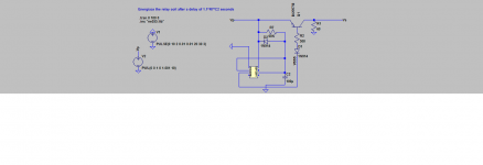
I have a starting point schematic, of a simple 555 timer circuit that stays on once the timer has expired. The signal can be used to power a couple relays, say like on a slow charge circuit?
I have a starting point schematic, of a simple 555 timer circuit that stays on once the timer has expired. The signal can be used to power a couple relays, say like on a slow charge circuit?
Attachments
Last edited:
Soft start is different from slow charge -- soft start takes very little time, while the slow charge takes a lot more time, which brings in different issues. I guess that the slow charge is really more about using thermistors for long time periods before switching them out as well as relay and transformer ratings.
AFAIK, the timer must allow the thermistor to cool to the point that inrush to the capacitor bank is still managed. Hence, a timer circuit is needed to enforce a delay in which the thermistors may cool down to operating temp.
AFAIK, this is 50% of initial resistance, which implies that a slow charge ought to be built around using thermistors in series, whose values at 50% of rated resistance will still act as inrush current limiters. Perhaps this is a bit conservative, but it guarantees a safe start every time.
Then the timer needs to be at least this cool down time. Larger cap banks on high biased amps would need more time to ensure that the relay contacts are not damaged when they are switched.
The above circuit can be easily built P2P -- no real PCB is necessary.
Hi apnneto,
Thanks for the circuit! It solved a problem in the one I posted: The cap attached to pin 5 is needed for stability -- my circuit would not simulate above a 10V Vp. Included is the LTspice file with the fix.
KatieandDad,
yes, that is fundamentally why I abandoned the idea of using resistors to limit the inrush. That circuit needed the load to be switched out to allow the caps to charge, then the load was switched in later. It required a very large number of resistors to slowly charge two banks of caps, one per channel, each being 176000uF.
IMO, the key element is to ensure that the timer that bypasses the thermistors is longer than the time that the thermistor takes to cool to 1/2 of the original resistance. Then you can use two in series, so that the design resistance is 1/2 the original resistance. There should be no problem filling the caps under load, as the series resistance is very low when the thermistors are hot.
Attachments
- Status
- This old topic is closed. If you want to reopen this topic, contact a moderator using the "Report Post" button.
- Home
- Amplifiers
- Power Supplies
- Slow charge