Hi,
I've had a search with google but all that I have found is somewhat over my head.. I think I need really really simple
Basically, I am thinking of replacing the power supply caps in my Rega Maia (stereo power amp), as it seems to be gutless, after listening to an old TMA 60P, the psu caps in the 60P are Elna. The old ones in the Rega are not such good quality, so I am told, and decent new caps should make a nice difference.
Rather than just de-solder and re-solder in new ones I would like to understand, even just a little as to what is going on in the case.
Simple questions, I hope you understand what I'm on about... I hope you can reply with very simple answers..
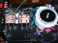
I have two toroidal transformers in the Maia, and one circuit board, does not look like a dual mono, as everything is on one board, looks like mashed in together, to the untrained eye. Anyway as I understand so far, if at all:
240V ac comes in, gets transformed down, then rectified splitting the + and the -, then the caps come in to filter (I don't know what) and smooth closer to a straight line dc, I guess 3 for the + and 3 for the - as there are 6 big caps if I remember rightly.
Do I get one rail of +(=x)dc and another rail of -(=x)dc, so the amp output is AC once again, made from the values inbetween the + and - dc rails ?
The smoother the dc rails are, the more accurate the ac output should be..?
I guess I will have to check the transformers to see if they have one out put each, so each transformer does one rail.. Or, each transformer has two out puts and so one transformer for the left +&- rails and one for the right +&- rails?
Appreciate you reading, and I look forward to reading a nice simple answer,
Many thanks in advance,
Cheers
DC
I've had a search with google but all that I have found is somewhat over my head.. I think I need really really simple
Basically, I am thinking of replacing the power supply caps in my Rega Maia (stereo power amp), as it seems to be gutless, after listening to an old TMA 60P, the psu caps in the 60P are Elna. The old ones in the Rega are not such good quality, so I am told, and decent new caps should make a nice difference.
Rather than just de-solder and re-solder in new ones I would like to understand, even just a little as to what is going on in the case.
Simple questions, I hope you understand what I'm on about... I hope you can reply with very simple answers..
I have two toroidal transformers in the Maia, and one circuit board, does not look like a dual mono, as everything is on one board, looks like mashed in together, to the untrained eye. Anyway as I understand so far, if at all:
240V ac comes in, gets transformed down, then rectified splitting the + and the -, then the caps come in to filter (I don't know what) and smooth closer to a straight line dc, I guess 3 for the + and 3 for the - as there are 6 big caps if I remember rightly.
Do I get one rail of +(=x)dc and another rail of -(=x)dc, so the amp output is AC once again, made from the values inbetween the + and - dc rails ?
The smoother the dc rails are, the more accurate the ac output should be..?
I guess I will have to check the transformers to see if they have one out put each, so each transformer does one rail.. Or, each transformer has two out puts and so one transformer for the left +&- rails and one for the right +&- rails?
Appreciate you reading, and I look forward to reading a nice simple answer,
Many thanks in advance,
Cheers
DC
Once you go past the rectifiers, there's no more AC.. Only DC with small ripples. The better the filtering (bigger caps, choke, etc) the smaller the ripples and will come closer to the DC output of a battery which is ripple-less.
I think what you need is visual presentation of how rectification and filtering works. I bet Youtube is loaded with those.
I think what you need is visual presentation of how rectification and filtering works. I bet Youtube is loaded with those.
Thanks for your replies,
Yes that is the bit I wanted to check, past the rectifiers there is dc with small ripples, one dc voltage at +20V and another at -20V.. yes? (20V just as an example value)
Then the amp uses the + and the - dc values to create the ac output value that goes to the speakers?
Before I change the caps I will prob take one out of circuit and measure it, just to see if it has aged and gone out of spec.
Thanks again for replying.
A bipolar supply ( + & - & G) will be 2 "Rails" of supply.
This can be accomplished by using 2 Full Wave Bridge Rectifiers.
Download the First Watt F4 manual and scroll to the last few pages, there is a VERY easy to understand bipolar power supply that I built from scratch off of the diagram.
This can be accomplished by using 2 Full Wave Bridge Rectifiers.
Download the First Watt F4 manual and scroll to the last few pages, there is a VERY easy to understand bipolar power supply that I built from scratch off of the diagram.
Attachments
Hey cool, this is speed learning now :-D
Nice pic, makes it look pretty straight forward building a power supply!
Well would take me an absolute age, but looks managable.
Must say I came to the channel schematic first and thought :-o what the .... !
But the psu one, yes I follow it, just.
Gonna look up bipolar supply
Nice pic, makes it look pretty straight forward building a power supply!
Well would take me an absolute age, but looks managable.
Must say I came to the channel schematic first and thought :-o what the .... !
But the psu one, yes I follow it, just.
Gonna look up bipolar supply
With Mains powered equipment, the transformer achieves a second and more important job.
The Transformer ISOLATES the Mains Voltage from the operator side.
This is a very important Safety concern.
Auto transformers MUST not be used, since they do not isolate.
A Variac is an adjustable auto transformer.
The Transformer ISOLATES the Mains Voltage from the operator side.
This is a very important Safety concern.
Auto transformers MUST not be used, since they do not isolate.
A Variac is an adjustable auto transformer.
In the beginning it looks unlogical , but in fact it's easy: remember dat the (virtual ground)
ain't the lowest voltage, the negative rail is, so the ground is positive .... which is with npn and pnp's and placing from elco's is something to think about. Look and read at some circuits, where they explain it, step by step and understand it, since a human things the lowest is the grounding.
Which btw never has the value of zero volts, goodluck , greets richard
- Status
- This old topic is closed. If you want to reopen this topic, contact a moderator using the "Report Post" button.
- Home
- Amplifiers
- Power Supplies
- Really simple psu explanation for amps.. where to look?