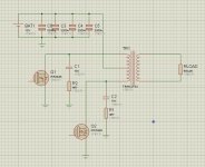
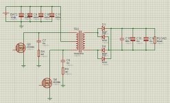
im trying to get 310volt dc from 12 v dc. im using push pull topology. i have some strange signals on drains of the mosfets when i try to rectify the ac output of the transformer.
when i connect a load directly to the transformer ac output, drain voltage and gate signal are like on the pictures 1 .
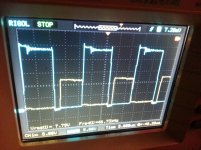
but when i rectified the ac output of the transformer with bridge configuration(4xfr107 diode) and connect the same load drain voltage and gate signal are like on the pictures 2
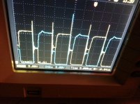
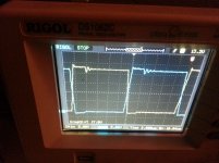
in picture 3 and 4 are drain voltages with the load connected directly to output of the transformer without rectified (picture 3) and load connected to the rectified output of the transformer (picture 4 )
when i connect a load directly to the transformer ac output, drain voltage and gate signal are like on the pictures 1 .
but when i rectified the ac output of the transformer with bridge configuration(4xfr107 diode) and connect the same load drain voltage and gate signal are like on the pictures 2
in picture 3 and 4 are drain voltages with the load connected directly to output of the transformer without rectified (picture 3) and load connected to the rectified output of the transformer (picture 4 )
by the way can some please explain me how to attache the pictures here. when i try to attach im getting this error massage.
Your submission could not be processed because a security token was missing.
If this occurred unexpectedly, please inform the administrator and describe the action you performed before you received this error.
Your submission could not be processed because a security token was missing.
If this occurred unexpectedly, please inform the administrator and describe the action you performed before you received this error.
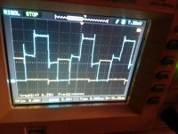
First thing I can see is that duty cycle is changing, and the power supply is still running unregulated (you haven't mentioned LC output filters so far), correct?
duty cyle is not changing. in the pictures it could be change because im changing the duty cyle manually . the pictures i have taken maybe have different duty cyle cuz i have taken the photos with different duty cyles.
but the problem is the same. if a rectified the output of the transformer drains are not chasing the gates duty. even with very small duty cyles the drain voltages are always like in the picture 4. with all duties it is the same.
if i ddont rectify drain are chasing the gates duty.
yes i didnot put a filter yet. im not using a feedback loop yet. im manually applying a duty with a potentiometer.
And your contoller/timer (IC)?
sg3526 running at 100 khz. so my frequency on transformer is 50 khz.
primary 3+3 turns and the secondry is 102 turns.
ei33 tansformer. pc atx one.
From what I can infer, everything looks normal but the quality of your scope, the way you synchronize it and the way you display the two channels doesn't help in figuring out what is going on.
In the first pics, the voltage returns to the magnetizing current times your resistive load during the inactive periods.
When the rectifier is connected, the filter cap holds the peak value, and the magnetizing current is unhindered and pushes the voltage to that peak value during the dead times.
Note that controlling the duty cycle with this type of configuration is pointless: the voltage will always tend to the peak value, changing the duty cycle will merely increase the losses.
You need to add a proper filter choke if you really want to control your converter that way
From what I can infer, everything looks normal but the quality of your scope, the way you synchronize it and the way you display the two channels doesn't help in figuring out what is going on.
In the first pics, the voltage returns to the magnetizing current times your resistive load during the inactive periods.
When the rectifier is connected, the filter cap holds the peak value, and the magnetizing current is unhindered and pushes the voltage to that peak value during the dead times.
Note that controlling the duty cycle with this type of configuration is pointless: the voltage will always tend to the peak value, changing the duty cycle will merely increase the losses.
You need to add a proper filter choke if you really want to control your converter that way
when i rectified my transformer output draing voltages are not chasing the gates duty. (picture 4) even with very small duty cyles draing voltages seem to be cross conductioning. im mean gates are closing and opening sharply but the drain voltages are linearly incresing and decreasing. from 0 volts to 2 Vdc.From what I can infer, everything looks normal but the quality of your scope, the way you synchronize it and the way you display the two channels doesn't help in figuring out what is going on.
how can i eliminate this?When the rectifier is connected, the filter cap holds the peak value, and the magnetizing current is unhindered and pushes the voltage to that peak value during the dead times.
what is duty cyle for? it is for to regulate the output voltage? right? if so i m eliminating the output voltage control now (at least im doing that manually, not with sg3526) so this not impoartant for me now. whether my output regulated or not. i have tried the curcuit also with a 2.2 mH,330 uH, 100 uH chokes and same capacitors. but it didnt help me to get the proper drain voltages. when i rectified the output drains are not coming after the gate duty. im not interested with my output voltage ripple or current ripple right now.
as i understood from this this is causing the drain voltages going 2 Vdc. if so how can eliminate this?the voltage will always tend to the peak value,
Last edited:
I don't see that in your oscillograms, but I may have misinterpreted them.when i rectified my transformer output draing voltages are not chasing the gates duty. (picture 4) even with very small duty cyles draing voltages seem to be cross conductioning. im mean gates are closing and opening sharply but the drain voltages are linearly incresing and decreasing. from 0 volts to 2 Vdc.
how can i eliminate this?
You should post them again, but with an unambiguous sync (no opposite polarities overlaid) and gate drive well separated too .
I don't think you have cross-conduction. If you had, the power transistors would heat up and blow very quickly.
To be certain, you need to measure both drain voltages at the same time on your scope: if they are low at the same time, this means cross-conduction, but even then, this might not be problematic if it is short enough to be absorbed by the leakage inductance of the transformer.
In general, duty cycle controls the output voltage, but it requires a proper filter choke.what is duty cyle for? it is for to regulate the output voltage? right? if so i m eliminating the output voltage control now (at least im doing that manually, not with sg3526) so this not impoartant for me now. whether my output regulated or not. i have tried the curcuit also with a 2.2 mH,330 uH, 100 uH chokes and same capacitors. but it didnt help me to get the proper drain voltages. when i rectified the output drains are not coming after the gate duty. im not interested with my output voltage ripple or current ripple right now.
If you just want to make an equivalent electronic transformer, the duty cycle can be maximized to almost 100%. The dead times are just required to avoid cross-conduction, but with MOSFets, they can be very small.
I think you are concentrating on false problems and your converter is in fact working (almost) properly.
During normal operation, the drain voltage will be leading the gate drive, but this is normal, at least for duty cycles <100%
I don't see what you mean thereas i understood from this this is causing the drain voltages going 2 Vdc. if so how can eliminate this?
Last edited:
really?I think you are concentrating on false problems and your converter is in fact working (almost) properly.
the drain voltages are on the picture four. are they normal?
if so when i change my duty from %10 to %40 with a 60 watt load the output is not changing is it normal also ?
(im checking gate signal and they are changing)
Last edited:
really?
the drain voltages are on the picture four. are they normal?
if so when i change my duty from %10 to %40 with a 60 watt load the output is not changing is it normal also ?
no no its changing sorry. i just need some more turns on sekondry. i have got max 272 v dc with a 60 watt load.
what could you say about output rectifiers dieodes current rating. im plannin to have 150 watt power at 310 v dc.
Yesreally?
the drain voltages are on the picture four. are they normal?
As I said above, reducing the duty cycle increases the losses and therefore marginally reduces the output voltage, but it isn't a proper control method.if so when i change my duty from %10 to %40 with a 60 watt load the output is not changing is it normal also ?
The DC should stay at the near maximum value
In principle, moderately fast 0.25A/ 400V diodes should suffice, but given the price of UF4007 for example, there is no reason to be so tightwhat could you say about output rectifiers dieodes current rating. im plannin to have 150 watt power at 310 v dc.
Yes
As I said above, reducing the duty cycle increases the losses and therefore marginally reduces the output voltage, but it isn't a proper control method.
The DC should stay at the near maximum value
In principle, moderately fast 0.25A/ 400V diodes should suffice, but given the price of UF4007 for example, there is no reason to be so tight
with the rectification i have a problem. im using fr107 (diodes because i have them from pc atx power suppilies)
when i connect a 60 watt load everything is ok. i have tested it half an hour and there was no problem. nothing is getting hot.
but when i connected a 90 watt resistive load again my diodes are getting hot after 1 min and they are broken. what could be the reason for this?
if i do a proper filtering (lc filter at the output) can i eliminate these diodes are getting broken.
Toyer, Elvee is saying that without an output inductor what you made is a peak detector.
You have to add an inductor around 50mH or so to your output to get the voltage to vary with PWM.
ok. how can i calculate that inductor value exactly?
- Status
- This old topic is closed. If you want to reopen this topic, contact a moderator using the "Report Post" button.
- Home
- Amplifiers
- Power Supplies
- push pull converter 12Vdc to 310 V dc drain voltages problem,im confused