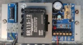
This is probobly an easy one but i cant get my head around it. I picked up this "UPS Module" on eBay, its basically a linear regulator supply but its intended to be connected to a sealed lead acid battery as a battery backup unit. Its got a 12v AC transformer, and the regulator is set for 13.6v via an adj pot to charge the battery. I connected an old battery that was down at ~6v and shortly after one of the resistors started to cook @120c. I assume the battery has a dead cell and is drawing too much current.
I am trying to map out the circuit and figure out how it works, the regular is a 7805, (why on earth would you use a fixed 5v part as an adjustable regulator for a 12-14v circuit?), output passes through a 1amp fuse, then two resistors and a reverse biased diode in parallel. I assume the logic being charge going in is current limited via the resistors, and power coming out passes through the diode unimpeded. The resistors have me perplexed, they read 47ohms, and 10ohms. The 10ohm resistor being the one that fried, so i'm not 100% sure if it was 10ohms before hand.
Can anybody tell me why they would use two resistors in parallel, was it to spread out the load and heat? And what kind of resistance should i be using to charge a sealed lead acid battery?
Attachments
Have you got the circuit correct as 10 ohm could be correct but i cant reconcile its wattage .
Wiki suggests a (good) 12V lead acid with near zero charge has a voltage of 10.5V , so these limiting resistors will have 13.6V minus 10.5V = 3.1V max across them . ( VxV )/R ......47ohm = 0.204W OK
......10ohm = 0.961 W not OK
47ohm parralled with 10ohm = 8.246ohm so max charge current would be 3.1/8.246 = 0.376A .
Last edited:
Thanks for the reply, i'm not 100% on the value as its a crispy brown colour now, all i can do is measure it. The 47ohm is fine which implys to me they were not the same value.
Physically they look like 1/4w resistors to me, which i agree doesn't make much sense. I had a quick peek inside the house alarm box to see what it had and found a 4.7ohm 5w wire wound cement block resistor in its circuit, that makes more sense to me. These two **** ant 1/4 watts i just don't get.
I've googled various trickle charging circuits based on 7800 and lm317 regulators and almost all of them had no resistor between the output and battery so i am even more confused now. Battery datasheets were little use, all i can find is the peak charge rate from dead flat is ~2.1amps, and i know that battery was down around 6v when i initially connected it up, hence resistor went bye bye. The circuit has a 12v 1amp transformer, a 7800 series regular which i belive can do 1amp, and a 1amp fuse in series before the battery so again, those two 1/4w resistors make no sense.
Question still remains, what value do i put in there?
Any fixed regulator can be adapted for a variable output by adding a couple of resistors. The fixed voltage replaces the 1.25v reference found in the LM317.I am trying to map out the circuit and figure out how it works, the regular is a 7805, (why on earth would you use a fixed 5v part as an adjustable regulator for a 12-14v circuit?),
Does the replacement resistor need to be the exact original value? I might suggest (if its purpose is current-limiting) that you select a value suitable for the battery you will be using.
- Status
- This old topic is closed. If you want to reopen this topic, contact a moderator using the "Report Post" button.
- Home
- Amplifiers
- Power Supplies
- Sealed lead acid power supply circuit