Hi Ales,
Is it possible to make an extra "I" (Vin) connection in the trace from I to C15 (position near C3) and a GND connection next to it?
In this way it easier to connect to a board with only GND V+ entrance. Since you van supply Vin en GND easy through the extra Vin and GND.
Gr GJ
Is it possible to make an extra "I" (Vin) connection in the trace from I to C15 (position near C3) and a GND connection next to it?
In this way it easier to connect to a board with only GND V+ entrance. Since you van supply Vin en GND easy through the extra Vin and GND.
Gr GJ
can the input and output caps be tantalum KEMET make?
Generally its said Tantalums are better than ceramics or may be equivalent to ceramic
Invalid Request
Sure ceramic capacitors can replaced with tantalum, but it is better to measure what kind of difference do you achieve with this action.
Hi Ales,
Is it possible to make an extra "I" (Vin) connection in the trace from I to C15 (position near C3) and a GND connection next to it?
In this way it easier to connect to a board with only GND V+ entrance. Since you van supply Vin en GND easy through the extra Vin and GND.
Gr GJ
Actually this is already realized, only downside is that then S- doesn't have any function.
I ordered some 3pin regulator PCBs and I'll see how they perform.
Best Regards,
Ales
Hi guys,
it has been a while since I did something on this PCB. Those 3pin regulators turned out bad, since I made too small package for TPS7A4700, so all PCBs ended up in trash.
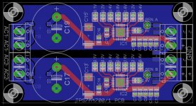
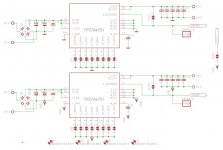
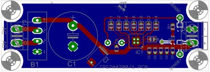
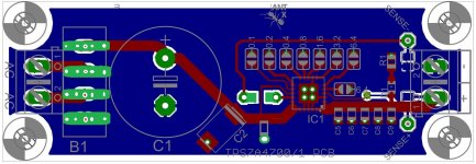
Now I have a design that uses two TPS7A4700/1, so with two PCBs you can get 3.3V, 5V and also symmetrical +/-12V voltage outputs (these voltages are for example, other values can also be configured). As you can see there is sense pin for each voltage output, but if one is not planing to use it can be shortened to output via solder jumper. I need to make a few more checks, then gerbers are going to fab.
BR,
Ales
it has been a while since I did something on this PCB. Those 3pin regulators turned out bad, since I made too small package for TPS7A4700, so all PCBs ended up in trash.
Now I have a design that uses two TPS7A4700/1, so with two PCBs you can get 3.3V, 5V and also symmetrical +/-12V voltage outputs (these voltages are for example, other values can also be configured). As you can see there is sense pin for each voltage output, but if one is not planing to use it can be shortened to output via solder jumper. I need to make a few more checks, then gerbers are going to fab.
BR,
Ales
Attachments
Interesting boards,
A few ideas... Better to make pcb with diodes or bridge in upper side of a pcb. Because if it is underside, it is not possible to use 3 or 4mm termal rubber and install it directly to the bottom wich can be used as a termal heatsink.
Can you do it in that way that can be breakable in 1 or 2 regulator...not as
2 pcs reg in one board.
For negative voltage did you mean TPS7A47... or TPS7A33..?
Can you do for output caps also for bigger dimension or just bigger gnd pads. Because pps caps or poscaps are not in small dimensions.
Like C1 and C2 ore maybe a little further. C2 and C3 are too close.
Maybe one smd led and resistor ath the output.
Still very interested mate Layout looks good. Have you made provisions for a heatsink(s) on the bottom?
The board is designed so that the heatsink can be mounted on the bottom.
Interested in a couple of boards, but why do we need 2 boards in order to get +/- 12v?
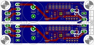
Because regulators are single output we need two of them to get symmetrical output. One PCB has two almost identical circuits.
Interesting boards,
A few ideas... Better to make pcb with diodes or bridge in upper side of a pcb. Because if it is underside, it is not possible to use 3 or 4mm termal rubber and install it directly to the bottom wich can be used as a termal heatsink.
I was also thinking about this option
")
Can you do it in that way that can be breakable in 1 or 2 regulator...not as
2 pcs reg in one board.
Noted. Though I still have to source cheap PCB manufacturer that offers this function.
For negative symmetrical output I mean to use TPS7A47, using this device makes sense to make PCB breakable.For negative voltage did you mean TPS7A47... or TPS7A33..?
Can you do for output caps also for bigger dimension or just bigger gnd pads. Because pps caps or poscaps are not in small dimensions.
I can do bigger GND pad on the other side of output line. But I don't know how PPS or POScaps would perform on the output, also maximum capacitance for PPS is 1uF (as I could found) and we need here 50uF. According to EVM they use here X5R capacitors.
Like C1 and C2 ore maybe a little further. C2 and C3 are too close.
Maybe one smd led and resistor ath the output.
Hope I will manage to squeeze all in.
Best Regards,
Ales
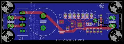
So this is what I came up with in couple of hours now. Instead of making breakable PCB I decided to make also single output PCB. This is because I will need symmetrical PSU for powering line drive from minidsp and single PSU for powering minidsp itself.
I also got the idea that single PCB could get daughter board with power transistor to get more current but I don't know how much would I degrade regulator specs.
BR,
Ales
I also got the idea that single PCB could get daughter board with power transistor to get more current but I don't know how much would I degrade regulator specs.
BR,
Ales
Attachments
So this is what I came up with in couple of hours now. Instead of making breakable PCB I decided to make also single output PCB. This is because I will need symmetrical PSU for powering line drive from minidsp and single PSU for powering minidsp itself.
I also got the idea that single PCB could get daughter board with power transistor to get more current but I don't know how much would I degrade regulator specs.
BR,
Ales
I believe you are using this pcb with dual secondary transformer with same voltage.
I generally have doubt about this Regulator is it stable? I am about to order 20 units of it for my DACs and Preamps hence a bit doubtful about this little chip.
Options:
1. Can I use single 47uf MLCC at the output? instead of 5 x 10uf MLCC?
2. I have fixed value requirement like 3.3V or 5V or 7V so can I use a super miniaturized pcb? all very close?
3. Im planning to use Metal film through hole resistors instead of surface mount as through hole resistors give less shot noise than the smd resistors.
As I haven't built any of this regulators I can't say if there are any stability issues.
1. Yes you can.
2. It is recommended that all the components are as close as possible to the chip. I have also seen designs where multiple TPS7A4700 are close to each other.
3. Interesting feature of this regulator is that it does not use external resistors. On my circuit there is only one resistor per regulator and that is for LED.
BR,
Ales
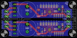
In the beggining of this thread I also got a hint about capacitor on NR pin (3). Now single output PCB has sensing for GND and positive voltage, capacitor size is also changed to use something better than MLCC. While symmetrical PCB has sensing only for positive voltage, though sensing for GND is directly on the screw terminal, eliminating ground currents present on GND plane.
I hope this is last revision before PCB manufacturing .
.
BR,
Ales
I hope this is last revision before PCB manufacturing
.BR,
Ales
Attachments
Can the two chips be configured as Tracking Regulators?
THx-RNMarsh
I think not as TPS7A4701 and TPS7A3301 require different resistor values for symmetrical voltage. For example TPS7A4701 has 76.8ohm and 10.2kohm for 12V and TPS7A3301 has 1.5Mohm and 162kohm -12V.
Can I ask you why would you need tracking regulator. As you can see this chip has programmable output, shorting pins to GND, so voltage can be setup very accurately.
Looking good Ales!
Thank you!
Looking good,
But I have some changes on my mind.... because of more flexibility and using different material.
At input ...possibility for diodes.... at NR pin also for posibility for smd, C3 on the other side, and maybe smd output cap gnd larger pads for posibility of different sizes of caps.
sorry picture is bad 5 min work, i hope you know what I mean.
Attachments
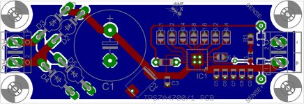 ( why such diodes position...
 We can install diodes vertical no need horizontal... and also stays possibilitY to use bridge. Just I suggested up.
MBR1045 have 5mm space length ( ok 2 of them must be bending a little more) By normal diode 2 of them are instaled vertically 2 of them horizontal. and bridge has also app 5mm space length.
Sorri to bother you.
Last edited:
Because it is impossible to fit them in such small space. You must understand that I do not wish to change outer PCB measures, that is why I also used bridge recitifier instead of diodes. Your wish to have bridge and diodes it is more like impossible so we need to decide diodes (normal ones or TO-220 style) or bridge?
so we need to decide diodes (normal ones or TO-220 style) or bridge?- Status
- This old topic is closed. If you want to reopen this topic, contact a moderator using the "Report Post" button.
- Home
- Amplifiers
- Power Supplies
- Low noise symmetrical PSU TPS7A4701 and TPS7A3301