Close, by a factor of 1000, it's ~8nH. Microhenries would be quite a lot of parasitic inductance.Does it say that I have the calculations all wrong, or that the 3u3F capacitor has esr=~13milli-ohms and esl=~8uH
Double checking that with |X_L|=w*L we should get 1Ohm at about 21Mhz, eyeballed from the plot. Does compute.
Also, 3.3uF read 1Ohm at ~58kHz, |X_C|=1/(w*C), about 15% off, OK
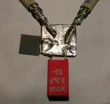
The test jig for the 3u3 + 150n combo looked like this :
Attachments
A sine generator and oscilloscope is basically all what's needed. They got to have some bandwidth, though. Finding SFR is quite easy (notably with dual channel scope to see phase of generator vs DUT voltage, phase is zero at resonance).
If you have quality function generator that can do a good (steep slope) rectangular wave you can also use a direct pulse measurement to get estimates for ESL and ESR : Measuring Capacitor ESR and Inductance
Pretty useless though if your step function is compromised/ringing and your scope probes aren't calibrated for flat/non-ringing response. And the scope need to be very a fast one, of course).
Andrew, for ESR measurement of electrolytic and tantalum capacitors from 1- 10000 uF, THIS is quite satisfactory. It is possible to mesure down to 0.010R (10 mili-Ohm).
Bottom resistor should equal generator's output Z (usually 50R).
You can calibrate your setup with 1R resistor and recheck with 0.22R or similar resistor with known value.
Scope is not critical, but you will need generator with fast rise time.
Bottom resistor should equal generator's output Z (usually 50R).
You can calibrate your setup with 1R resistor and recheck with 0.22R or similar resistor with known value.
Scope is not critical, but you will need generator with fast rise time.
Last edited:
Stormsonic's link shows the same method than what is used in the article I referenced to, good to see.
The equipment's requirements for the sinusodial test are less stringent than for the pulse test if your want to check for ESL (specs can be figured out from the D.C.Smith article, plus one can run a simulation to see what about to expect). The flat bandwidth of the sine generator and scope should be about 5x of whatever frequency you want to test (so 50...100Mhz would be great, the generator being the harder part).
You should do a null test before, using a known low inductance 1R or 0R1 resistor (flat/bulk film or carbon comp type, not a spiraled metal film, let alone a wirewound). If you record amplitude values you can use that to scale and normalize you actual results if you need that (normally, it's enough to find amplitude high and low points, then calculate ESL).
For short lenghts (<30cm) cable/connector impedance mismatch is not a severe problem (in my jig I used 30cm sections of 50Ohms cable while the analyzer feed is 75Ohms, still flat enough to tens of MHz). The injection point to the DUT is of course really important.
- Status
- This old topic is closed. If you want to reopen this topic, contact a moderator using the "Report Post" button.