Sorry, it was late and I locked in on the 431 as...
hi hearinspace, thanks for your reply. i have read these in the datasheet. none of them can supply a voltage higher than 40v.
The correct answer here, and no offense, is stop using the simulator and start reading datasheets and basic literature. You will not learn electronics from a simulator - it is a 'garbage in -> garbage out' device. Most of the components used in it are represented by models which are in most cases (I'd say 99%) valid only for the expected use of the device. If it's not connected correctly, the results will be nonsense, and rarely represent what will happen in a real circuit. This is why you need to understand the basics of a circuit before you even attempt simulating it, otherwise you will simply not know how to interpret the results of the simulation, not what to look for if they are unexpected. This has been said over and over on this forum, and apparently it always needs to be said again.
In your circuit, there are basic errors.
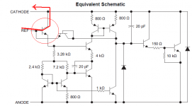
In the original one, the TL431 has no supply. It is a a shunt regulator, which is really a sort of zener diode replacement (albeit adjustable). There is a reason whu it is drawn as a zener diode! So, it needs to have a supply of current through it.
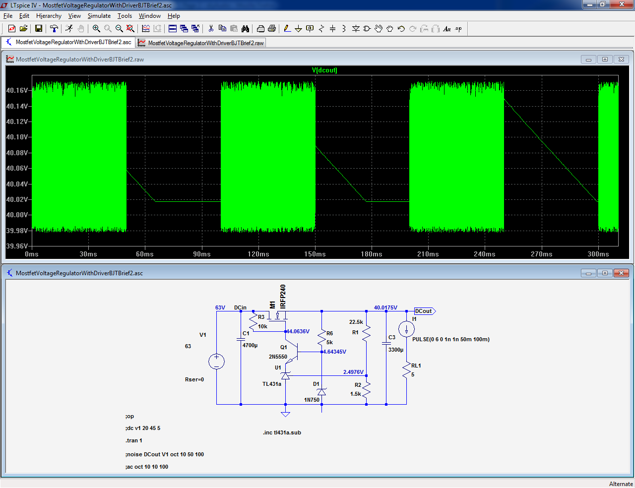
Secondly, there is no need for an added NPN transistor. Although in principle the schepatic could work with it, it can't work woth a TL431 simply because a TL431 can only go as low as 2.5V, and the B-E treshold of the transistor is ~0.7V. So, it will be permanently turned on to some extent, while the TL431 will essentially do nothing. The fact that the lowers voltage the TL431 can regulate is 2.5V (the value of it's internal reference) is well and clearly stated in it's datasheet (with examples of use!) and the datasheet is available from literally hundreds of places on the web. This clearly shows you didn't bother to read it.
Since the TL431 can go up to some 36V, but of course you don't want to use it at it's limit. the simplest way to extend it's voltage handling capability for your case is to add a zener diode in series. It should be for a voltage less than your intended output voltage, and 2.5V plus it's value is the minimum you can get with that circuit, 36V plus it's value is the maximum (again this is for the highest voltage on the TL431). There is no need to do anything special with thermal compensation of the zener - the TL431 ia an active device and it's regulation input is actually a feedback node. It will correct for any thermal drift of the zener.
Again - using a simulator is no shortcut to designing circuits for people who can't design them without one. Especially a simple one like yours - it's design can be done on paper in 5 minutes or
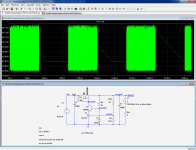
ilimezn, the question is how to get it thermally stable. the circuit works in simulation as well as in real world experiment. the only problem with it is the drift.
is there anybody who care for the 431 behavior when its working condition is out of the spec?
"Although in principle the schepatic could work with it, it can't work woth a TL431 simply because a TL431 can only go as low as 2.5V, and the B-E treshold of the transistor is ~0.7V. So, it will be permanently turned on to some extent, while the TL431 will essentially do nothing. The fact that the lowers voltage the TL431 can regulate is 2.5V (the value of it's internal reference) "
Thanks for the clarification. My suggestion was half baked and not thought out.
hi hearinspace, thanks for your reply. i have read these in the datasheet. none of them can supply a voltage higher than 40v.
You can easily use the 431 to build a regulator for voltages many times that, or, a single transistor and a few other passive parts can do it. . . . .
If you don't get what you want from your regulator I suggest you try searches like this one. There's a mountain of good info out there, trouble is there's a mountain of crap mixed in with it. You have to have patience sorting them out and find people whose advice you can trust. Best of Luck!
Can I also point out that the 431 is pretty bloody hopeless at such high voltages?
Whatever the basic reference merits, by the time you are using it up at 30+Vout you've divided it's available (and already-miserable) gain by over 10x , IOW you're playing with a reg with about 20dB of feedback and conseuqntly poor regulation. The LM317 can deliver 20dB upt ot perhaps 40dB (100x) better for minimal care at such supply levels - if you want to stay with jellybean parts.
Whatever the basic reference merits, by the time you are using it up at 30+Vout you've divided it's available (and already-miserable) gain by over 10x , IOW you're playing with a reg with about 20dB of feedback and conseuqntly poor regulation. The LM317 can deliver 20dB upt ot perhaps 40dB (100x) better for minimal care at such supply levels - if you want to stay with jellybean parts.
Last edited:
Thanks for the clarification. My suggestion was half baked and not thought out.
Hi Art,
Thanks for your suggestion. That is illuminating and I have redone the math and tried a few other variations based on the principle. Spice simulation is one important way for me to learn electronics and practice. One thing I cannot understand is what a role the 431 plays in the circuit in my second post, why the output voltage is still controllable by changing the resistance value of the divider, and the circuit performs just like what simulated. But, the simulation does not take temperature as a variable, therefore not predictable by simulation.
You can easily use the 431 to build a regulator for voltages many times that, or, a single transistor and a few other passive parts can do it. . . . .
If you don't get what you want from your regulator I suggest you try searches like this one. There's a mountain of good info out there, trouble is there's a mountain of crap mixed in with it. You have to have patience sorting them out and find people whose advice you can trust. Best of Luck!
Hearinspace, thanks again for your suggestion. The google search is not working in my country. It works sometimes, but not always. I will try it later.
Could you just post one of the circuits that you think good for beginner to learn, which use 431 and output high voltage?
Can I also point out that the 431 is pretty bloody hopeless at such high voltages?
Whatever the basic reference merits, by the time you are using it up at 30+Vout you've divided it's available (and already-miserable) gain by over 10x , IOW you're playing with a reg with about 20dB of feedback and conseuqntly poor regulation. The LM317 can deliver 20dB upt ot perhaps 40dB (100x) better for minimal care at such supply levels - if you want to stay with jellybean parts.
I have just checked the 317 datasheet on the TI site. The output cannot be > 37v. I will appreciate that you let me know how will you make an adjustable regulator 40-50v with a LM317?
You need to fix the transistor's base potential.
Now, it still requires some compensation to work properly
Attachments
http://www.diyaudio.com/forums/atta...regulator-how-get-thermally-stable-40vpsu.png
That's what I meant in my previous post.
That's what I meant in my previous post.
You need to fix the transistor's base potential.
Now, it still requires some compensation to work properly
hi Elvee, this is really help. thank you very much. will you be able to simulate the thetmal stability of the circuit? i think the zener can be replaced with a current source. do you think it will make it better?
A current source would make it worse not better as you want the base at a fixed voltage not one which tracks with the output (which would be positive feedback).
Stop messing about in spice and BUILD the damned thing, while I would add a cap across the zenner to lower the noise and another one to stabilise the loop, the basic idea will work and should be reasonably stable with temperature.
Regards, Dan.
Stop messing about in spice and BUILD the damned thing, while I would add a cap across the zenner to lower the noise and another one to stabilise the loop, the basic idea will work and should be reasonably stable with temperature.
Regards, Dan.
Here you are, but thermal stability is not exactly a priority if there are dynamic instablitieshi Elvee, this is really help. thank you very much. will you be able to simulate the thetmal stability of the circuit?
Noi think the zener can be replaced with a current source. do you think it will make it better?
Attachments
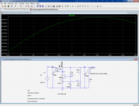
ilimezn, the question is how to get it thermally stable. the circuit works in simulation as well as in real world experiment. the only problem with it is the drift.
is there anybody who care for the 431 behavior when its working condition is out of the spec?
In your circuit you are just using the base-collector junction of one of the transistors inside the TL431 (as shown in the attachment) in series between your NPN transistor and the feedback divider.
If you want the TL431 to work in the way it is intended to, for starters the feedback polarity is wrong in your circuit even if you were to provide the TL431 with cathode current.
Attachments
A current source would make it worse not better as you want the base at a fixed voltage not one which tracks with the output (which would be positive feedback).
Stop messing about in spice and BUILD the damned thing, while I would add a cap across the zenner to lower the noise and another one to stabilise the loop, the basic idea will work and should be reasonably stable with temperature.
Regards, Dan.
hi Dan, i meant voltage souce formed by a current source and a load. thanks for your suggestion.
- Status
- This old topic is closed. If you want to reopen this topic, contact a moderator using the "Report Post" button.
- Home
- Amplifiers
- Power Supplies
- TL431 High Voltage Regulator - How to get it thermally stable?