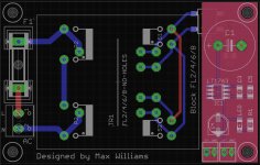
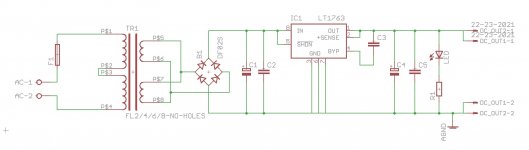
I'd like to design and build a simple low noise 5V power supply based on the LT1763. I've made a schematic and layout, does anyone have any feedback or suggestions for improvement?
TR1: Pads for Block FL2/FL4/FL6/FL8 or EI38 or EI30. Ideally 2x 6VAC.
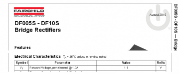
B1: VISHAY DFL1508S bridge rectifier
C1: Panasonic FC 1500UF, 16V
C2: 100nF X7R
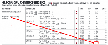
IC1: LT1763CS8-5, 5V fixed regulator
C3: C0G/NP0, 10NF, 100V
C4: Panasonic FK 100UF, 6.3V, SMD
C5: 100nF X7R
R1: Resistor for LED
LED: 1206 LED
Should I add a coil before the regulator? A snubber might be a good idea but I don't have the equipment to take measurements for this.
TR1: Pads for Block FL2/FL4/FL6/FL8 or EI38 or EI30. Ideally 2x 6VAC.
B1: VISHAY DFL1508S bridge rectifier
C1: Panasonic FC 1500UF, 16V
C2: 100nF X7R
IC1: LT1763CS8-5, 5V fixed regulator
C3: C0G/NP0, 10NF, 100V
C4: Panasonic FK 100UF, 6.3V, SMD
C5: 100nF X7R
R1: Resistor for LED
LED: 1206 LED
Should I add a coil before the regulator? A snubber might be a good idea but I don't have the equipment to take measurements for this.
Attachments
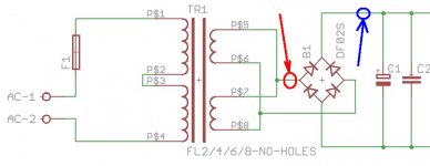
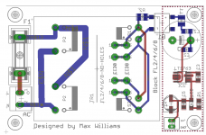
Perhaps you might consider adding a series resistor in the Red branch of the attached schematic, and you might also consider adding a ferrite bead in the Blue branch.
The resistor reduces the magnitude of the current peaks through the diodes, reducing the dV/dt slope of the zig-up piece of the ripple waveform. It also forms a lowpass filter (with C1 + C2 + Rdiode) which reduces the amount of high frequency noise passed from mains to IC1 input. The voltage dropped across this resistor eats into the voltage headroom ("dropout voltage") of the regulator, so carefully choose its resistance based on minimum mains voltage, maximum load current, maximum output voltage, and maximum regulator "dropout" specification. And I suggest you choose its wattage to be at least 3x higher than its theoretical power dissipation, both for long term reliability and also to avoid burning your finger when servicing.
The ferrite bead acts as a (lossy) resistor at high frequencies, further reducing RF noise conducted from mains into IC1.
Attachments
Thanks for the suggestions!
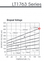
OK. Can you help me calculate it? The transformer outputs 6V when loaded and about 8V with no load. Current is limited to 500mA because the is the maximum the regulator will do. The regulator has a Low Dropout Voltage, 300mV. Maybe 2-4 ohms at 1w?The resistor reduces the magnitude of the current peaks through the diodes, reducing the dV/dt slope of the zig-up piece of the ripple waveform. It also forms a lowpass filter (with C1 + C2 + Rdiode) which reduces the amount of high frequency noise passed from mains to IC1 input. The voltage dropped across this resistor eats into the voltage headroom ("dropout voltage") of the regulator, so carefully choose its resistance based on minimum mains voltage, maximum load current, maximum output voltage, and maximum regulator "dropout" specification. And I suggest you choose its wattage to be at least 3x higher than its theoretical power dissipation, both for long term reliability and also to avoid burning your finger when servicing.
I was going to use an coil at the blue arrow, this one. Since a coil and a ferrite bead are just both inductors, does one preclude the other? Can you use both? Would this one be suitable?The ferrite bead acts as a (lossy) resistor at high frequencies, further reducing RF noise conducted from mains into IC1.
The transformer outputs 6V when loaded and about 8V with no load. Current is limited to 500mA because the is the maximum the regulator will do. The regulator has a Low Dropout Voltage, 300mV. Maybe 2-4 ohms at 1w?
{ [ ((6 x 0.95) x sqrt(2)) - (2 x 1.1) ] - 5.125 } = 0.736V across the LT1763 (with no Red resistor)
Subtract the LT1763 minimum dropout voltage (0.41 volts) and you get the voltage across the Red resistor: 0.326 volts
(0.326V / 0.5A) = 0.652 ohms. Round to nearest E12 standard resistance value: 0.68 ohms
Dissipation rating = (0.5A x 0.5A x 0.68R) x 3 = 0.51 watts. Me, I'd go ahead and use a 1W resistor. Just to provide a visual reminder on the PCB: "Hey, this resistor is high wattage so it might be hot! Be careful with it."
I recommend you read the Wikipedia article on ferrite beads; a ferrite bead is not "just an inductor". Rather, ferrite beads are lossy circuit elements at high frequencies; they dissipate power. Inductors, being lossless reactances, do not.
Attachments
Last edited:
OK thanks for your help Mark. I'll use this resistor at the red point, this Ferrite Bead and this inductor at the blue point.
Hi Max,
I don´t know how important electrolytic ESR is in this circuit but you could also consider the use of Panasonic FM or FR types for C1 (approx. half the ESR compared with FC types). Endurance for FR types is 2000 h to 10000 h at
+105 deg. C.
I haven´t checked the prices, though
Karsten
I don´t know how important electrolytic ESR is in this circuit but you could also consider the use of Panasonic FM or FR types for C1 (approx. half the ESR compared with FC types). Endurance for FR types is 2000 h to 10000 h at
+105 deg. C.
I haven´t checked the prices, though
Karsten
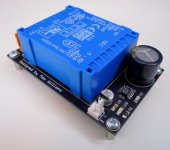
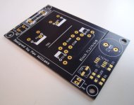
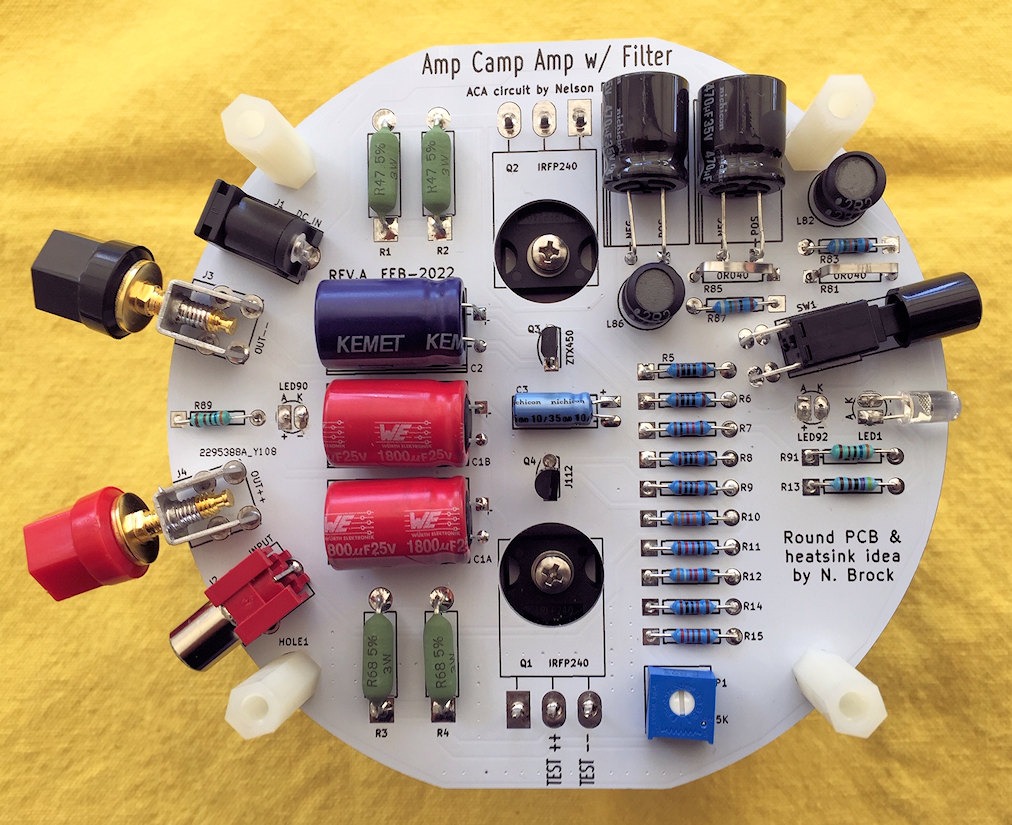
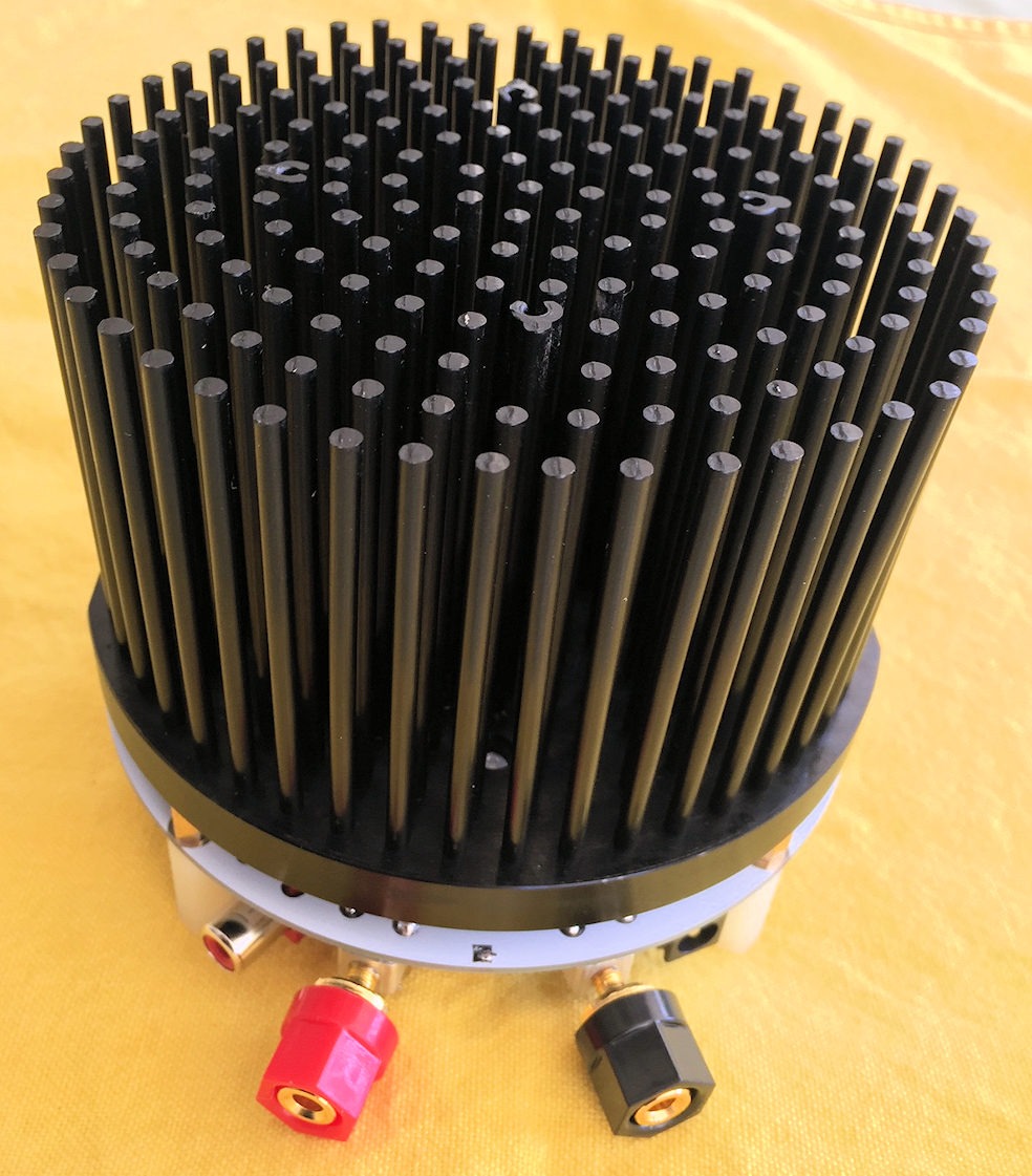
PCBs are done and I've assembled and tested it, it works!
I used a Block FL4/6 transformer and a Panasonic FC cap before the regulator (couldn't get larger value FR or FM caps in the lower height).
I did some ARTA measurements of my MDAC attenuator (which requires a 5V PSU) comparing this power supply and a battery, there was no measurable difference.
The BOM
F1: Fuse holder. Part URL.
TR1: Pads for Block FL2/FL4/FL6/FL8 or EI38 or EI30. Ideally 2x 6VAC. Part URL.
B1: VISHAY DFL1508S bridge rectifier. Part URL.
C1: Panasonic FC 1500UF, 16V. Part URL.
L1: INDUCTOR, 1210 CASE, 10UH. Part URL.
L2: FERRITE BEAD, 0.1OHM, 2A, 1206. Part URL.
C2: 100nF X7R, 1206 package.
IC1: LT1763CS8-5, 5V fixed regulator. Part URL.
C3: C0G/NP0, 10NF, 100V, 1206 package.
C4: Panasonic FK 100UF, 6.3V, SMD. Part URL.
C5: 100nF X7R, 1206 package.
R1: Resistor for LED, 1206 package.
LED: 1206 LED
I'll post Eagle PCB files later tonight.
Attachments
Please look over my Eagle Conversion to 120 Volts
Attached is my first trail to convert your 240-Volt 5-Volt Power Supply Eagle files to 120-Volt 5-Volt Power Supply Eagle files. I know NOTHING about Eagle. This is the first time I have try using Eagle, so please forgive me for ant mistakes. Let me know what you think of my attempt to make the necessary changes.
Attached is my first trail to convert your 240-Volt 5-Volt Power Supply Eagle files to 120-Volt 5-Volt Power Supply Eagle files. I know NOTHING about Eagle.
This is the first time I have try using Eagle, so please forgive me for ant mistakes. Let me know what you think of my attempt to make the necessary changes.Attachments
Can you fix it and then add this to this thread?
Can you fix these errors and then add them to this thread? I so knew to EAGLE,
I not sure what I'm doing when I made these changes. My plan is to take an
online course in how to use Eagle, any suggestions? Let US all know, I'm sure
all DIYAUDIO members would be interested. Take care.
Can you fix these errors and then add them to this thread? I so knew to EAGLE,
I not sure what I'm doing when I made these changes. My plan is to take an
online course in how to use Eagle, any suggestions? Let US all know, I'm sure
all DIYAUDIO members would be interested. Take care.
Hey MaxTR1: Pads for Block FL2/FL4/FL6/FL8 or EI38 or EI30. Ideally 2x 6VAC. Part URL.
Could you suggest any other pin-compatible transformer that is available at Mouser?
Also any part you use for R1 and LED?
Thanks for this nice project!
Last edited:
Max, would it possible to post the gerber as well as I do not have Eagle.And here are the Eagle PCB files if anyone wants to get their own PCBs made.
Hi @starcat!
I don't have gerbers, they are a pain to generate, so many options etc. I just use PCB service that accepts Eagle or kicad files. Sorry 🙂
You'd have to read the diagram and compare it to one of the Block models or EI38 or EI30 to be sure.
Sorry, I don't know, but as it states "Block FL2/FL4/FL6/FL8 or EI38 or EI30" should be enough info to find one I think.
I think just any 1206 package LED and resistor, about 1K.
would it possible to post the gerber as well as I do not have Eagle.
I don't have gerbers, they are a pain to generate, so many options etc. I just use PCB service that accepts Eagle or kicad files. Sorry 🙂
This transformer block should be equivalent and fit, I think.
You'd have to read the diagram and compare it to one of the Block models or EI38 or EI30 to be sure.
Could you suggest any other pin-compatible transformer that is available at Mouser?
Sorry, I don't know, but as it states "Block FL2/FL4/FL6/FL8 or EI38 or EI30" should be enough info to find one I think.
Also any part you use for R1 and LED?
I think just any 1206 package LED and resistor, about 1K.
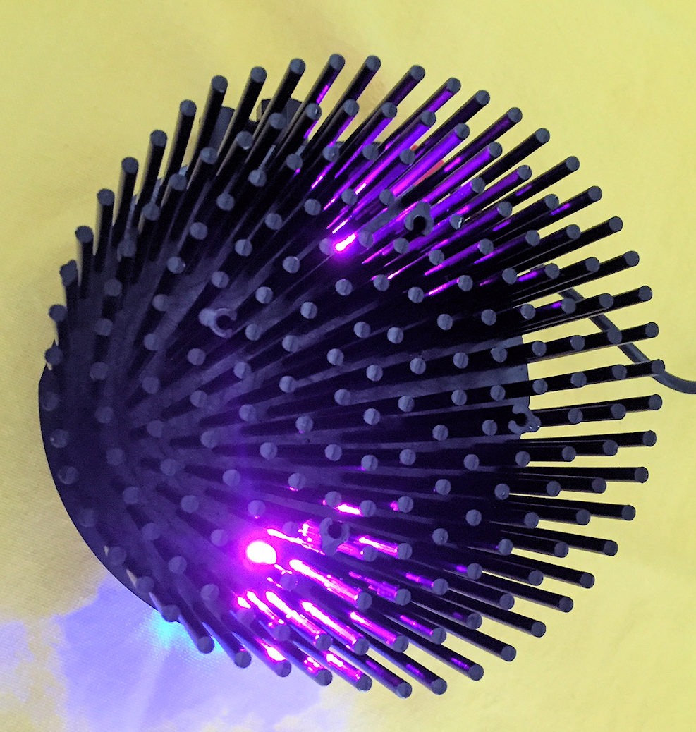
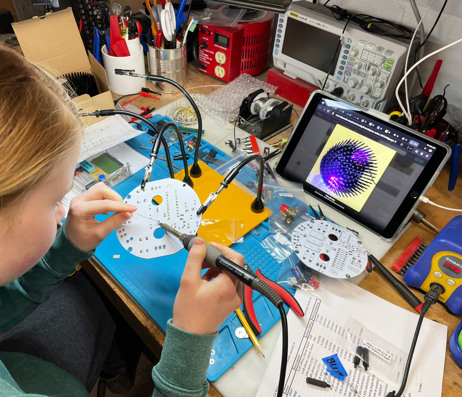
I export the (KiCad) layer called "Edge.Cuts" as part of the Gerber file .zip archive. Then the PCB fab calculates the exact board dimensions for me. For this board, the fab named JLCPCB calculated the dimensions are 119.92 by 115.00 mm. Patrick Farrell's 11 year old daughter built a pair of monoblocks from two of these PCBs.
- Home
- Amplifiers
- Power Supplies
- A simple LT1763 based 5V PSU